


JL AUDIO 1000/1 21
APPENDIX E:
1000/1 Specifications
GENERAL SPECIFICATIONS:
Recommended Fuse Value: 100A
Recommended Fuse Type: ANL
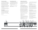
INPUT SECTION:
Input Type: Differential-balanced with RCA jack inputs
Input Range: Switchable from 200mV - 2V RMS to
800mV - 8V RMS
AMPLIFIER SECTION:
Amplifier Topology: H-Bridge, Class D Mono
with impedance optimization and patented
discrete drive circuitry
Power Supply:Pulse width modulation-regulated
switching power supply
Rated Power: 1000W RMS x 1 @ 1.5 - 4Ω (11 - 14.5V)
THD at Rated Power: <0.05% @ 4Ω,50 Hz
Signal to Noise Ratio:>95 dB referred to rated power
(A-weighted,20 Hz - 20 kHz noise bandwidth)
Frequency Response:5 - 250 Hz (+0, -3 dB)
Damping Factor:>500 @ 4Ω/50 Hz,>250 @ 2Ω/50 Hz
CROSSOVER SECTION:
Amplifier Low-Pass Filter: State-variable, 12 dB/octave
Butterworth or 24 dB/octave Linkwitz-Riley with
continuously variable cutoff frequency selection
from 40 - 200 Hz, defeatable
PREAMP OUTPUT:
2-Channel, with fully independent, state-variable,
12 dB/octave Butterworth or 24 dB/octave Linkwitz-Riley
filter with continuously variable cutoff frequency selection
from 40 - 200 Hz, defeatable
ADVANCED BASS CONTROL SECTION:
Parametric EQ:Single-band, fully parametric equalizer
with “Q” adjustment from 0.5 - 4.0,center frequency
adjustment from 20 - 80 Hz, boost adjustment from
0 to +15 dB and port for optional remote bass
boost control (RBC-1), defeatable
Infrasonic Filter:Fully variable, 24 dB/octave Butterworth
high-pass filter, cutoff frequency adjustable from
15 - 60 Hz, defeatable
DIMENSIONS:(LxWxH):
19.7" x 9.25" x 2.36" (500mm x 235mm x 60mm)
Due to ongoing product development,all specifications are
subject to change without notice.
20 JL AUDIO 1000/1
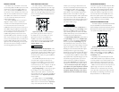
“MY AMPLIFIER’S OUTPUT FLUCTUATES WHEN I TAP ON IT OR HIT A BUMP”
Check the connections to the amplifier. Make sure that the insulation
for all wires has been stripped back far enough to allow a
good contact area inside the amplifier terminal.
Check the RCA connectors to ensure that both the center pin and
the outer shield are making good contact with the input jacks
on the amplifier.
“HOW DO I PROPERLY SET THE INPUT SENSITIVITY ON MY AMPLIFIER”
Please refer to Appendix B (page 14) to set the input sensitivity for
maximum, unclipped output.
APPENDIX D: TROUBLE SHOOTING (CONT.)