


performance in your system, listening in particular
to the mid-bass smoothness and impact to make
your determination.
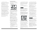
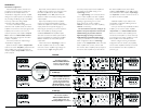
STATUS INDICATOR LIGHTS /
PROTECTION CIRCUITRY
There are three status indicator lights on the top
of the amplifier. These are as follows:
1) “Power” (Green): lights to indicate that the
amplifier is turned on and operating normally.
2) “Thermal” (Red): lights to indicate that the
amplifier has exceeded its safe operating
temperature, putting the amplifier into a self-
protection mode, which reduces the power output
of the amplifier. The red light will shut off and the
amplifier will return to normal, full-power operating
mode if the heat sink temperature drops back to a
safe level.
3) “Low Ω” (Amber): lights to indicate that the
impedance of the speaker load connected to the
amplifier is lower than the optimum load impedance
range for the amplifier.When this light is on, a
protection circuit engages and reduces the power
output of the amplifier.The amber indicator will also
light when a short-circuit is detected in the speaker
wiring (this can be a short between the positive and
negative speaker wires or between either speaker
wire and the vehicle chassis).
4) “Low V” (Blue): lights to indicate any dip in
supply voltage below 8 volts.The blue LED will
remain lit longer than the dip duration to better
alert the user to the problem. This will be
accompanied by a shutdown of the amplifier
(green LED will shut off) and a total loss of
output. Once the voltage rises above 9 volts,
the amplifier will turn itself on. Because voltage
dips occur in rapid succession, the typical behavior
will be a cycling of the amplifier on and off,
accompanied by flashing of the “Low V” blue LED.
If this is happening in your system, you will need to
investigate the cause of the voltage problem.This
could be a bad ground on the amplifier, battery or
alternator OR a faulty battery/charging system OR
a problem with a fuse holder or wire connection.
If you are unsure as to the cause of the problem,
please consult your JLAudiodealer or a qualified
automotive electrical specialist.
In marginal situations, a 1.0 Farad (or larger)
rapid-discharge capacitor connected in parallel to
the amplifier power connections may minimize
short-duration voltage dips in systems that are
having this problem.
Keep in mind that any large amplifier, like the
1000/1, places a very heavy demand on a vehicle’s
charging system when operated at its limits.Vehicles
with weak charging systems may need to be
serviced and/or upgraded to provide ample current
to a system including a 1000/1.
For information on troubleshooting this
amplifier, refer to Appendix D (page 18).
SERVICING YOUR JL AUDIO AMPLIFIER
If your amplifier fails or malfunctions, please
return it to your authorized JL Audio dealer so
that it may be sent in to JL Audio for service.
There are no user serviceable parts or fuses
inside the amplifier.The unique nature of the
circuitry in the JL Audio amplifiers requires
specifically trained service personnel. Do not
attempt to service the amplifier yourself or
through unauthorized repair facilities.This will not
only void the warranty, but may result in the
creation of more problems within the amplifier.
If you have any questions about the installation or
setup of the amplifier not covered in
this manual, please contact your dealer or the
JL AUDIO Technical Department for assistance:
(954) 443-1100
9:00 AM – 5:30 PM Eastern Time,
Monday – Friday
JL AUDIO 1000/1 11
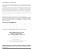
SUBWOOFER OUTPUT
The 1000/1 employs JL Audio's exclusive
Regulated, Intelligent Power Supply (R.I.P.S.) design.
This sophisticated power supply allows the amplifier
to produce its optimum power (1000 watts x 1)
over a wide range of speaker impedances.
Unlike conventional amplifiers that require a
specific impedance to produce optimum power, the
R.I.P.S.-equipped 1000/1 gives you the freedom to
use a variety of subwoofer configurations that
achieve final nominal impedances between
1.5 – 4Ω (without sacrificing power output or
sound quality).
The operation of the R.I.P.S. circuitry is entirely
automatic and adjusts itself every time the amplifier
is turned on according to the lowest impedance
present at the speaker load.There are no user
controls to configure.The system operates through
multiple stages of impedance optimization, choosing
the stage most appropriate to the actual impedance
of the speaker(s) you connect to it.
If you connect a load higher than 4Ω nominal
to the 1000/1, power will drop by half with every
doubling of impedance above 4Ω. If you connect a
load lower than 1.5Ω nominal to the 1000/1, the
amplifier protection circuitry activates a “safe”
mode which reduces amplifier power to protect
the circuitry from failure (the yellow LED on the
top of the amplifier will light to indicate that this
has happened). See page 11 for details.
Speaker loads below 1.5Ω nominal are not
recommended and may cause the amplifier output
to distort excessively.
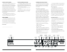
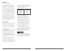
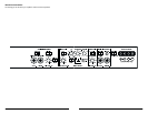
Speaker connections to the 1000/1 are
straightforward and take place at the far right of
the front panel.You will notice that there are two
“+” positive connections and two “–” negative
IMPORTANT
!
IMPORTANT
!
connections.This is to facilitate multiple speaker
wiring.The two positive and two negative
connections are connected in parallel inside the
amplifier. Connecting two speakers, each to one set
of positive and negative terminals, will result in a
parallel speaker connection. If only connecting one
pair of speaker wires, it is not necessary to use
both sets of connections.
Do not chassis ground any speakers connected
to this or any other JL Audio amplifier. Doing so will
cause the amplifier to go into protection and mute
the output.
The 1000/1's speaker connectors are designed
to accept 12 AWG – 8 AWG wire.
To connect the speaker wires to the amplifier,
first back out the set screws on the top of the
amplifier, using the supplied 2.5 mm hex wrench.
Strip 1/2 inch (12 mm) of insulation from each
wire and insert the bare wire end into the
receptacles on the front panel of the amplifier,
seating them firmly so that no bare wire is
exposed.While holding each wire in place, tighten
each set screw firmly, taking care not to strip the
head of the screw and making sure that the wire
is firmly gripped by the set screw.
Do NOT attempt to “bridge” two 1000/1’s or
combine their output to a single load in any
manner. Doing so will damage the amplifier(s).
Before reconnecting the battery ground and
turning the system on, verify that all control
settings on the amplifier are set according to the
needs of the system.
OUTPUT POLARITY SWITCH
Depending on the distance relationship of the
mid-bass speakers and the subwoofers in a
system, it can be desirable to reverse the polarity
of the subwoofer system in order to produce a
better transition between subwoofer and mid-
bass speaker output.The “Output Polarity” switch
allows you to peform this polarity inversion
without removing any wires. Simply flip the switch
from the “Normal” to the “Reversed” position.
Experiment with this switch to determine which
polarity produces the best overall bass
IMPORTANT
!
IMPORTANT
!
10 JL AUDIO 1000/1