


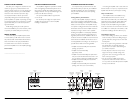
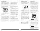

INPUT SECTION
The 300/2 has one input section, which contains a
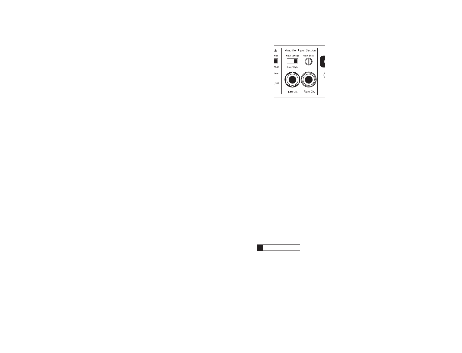
pair of RCA-type input jacks,an “Input Voltage”
switch and an “Input Sens.” rotary control.
1) Input Voltage Range:A wide range of signal
input voltages can be accommodated by the
300/2's input section (200mV – 8V).This wide
range is split up into two sub-ranges,accessible via
a switch located in the “Amplifier Input Section”.
The “Low” position on the “Input Voltage”
switch selects an input sensitivity range between
200mV and 2V.This means that the “Input Sens.”
rotary control will operate within that voltage
window. If you are using an aftermarket source unit,
with conventional preamp-level outputs, this is most
likely the position that you will use.
The “High” position on the “Input Voltage”
switch selects an input sensitivity range between
800mV and 8V.This is useful for certain high-output
preamp level signals as well as speaker-level output
from source units and small amplifiers.To use
speaker-level sources, splice the speaker output
wires of the source unit or small amplifier onto a
pair of RCA plugs.
The output of the amplifier will decrease for a
given input voltage when the “Input Range” switch
is placed in the “High” position. Conversely,the
output will be higher with the switch in the “Low”
position.While this may sound counter-intuitive, it is
consistent with the descriptions above.
IMPORTANT
!
2) Input Sensitivity Adjustment:Located next to
the “Input Voltage” switch in the “Amplifier Input
Section”nput section is a rotary control labeled
“Input Sens.”. Once the appropriate “Input
Voltage” range has been selected, this control can
be used to match the source unit's output voltage
to the input stage of the 300/2 for maximum clean
output. Rotating the control clockwise will result in
higher sensitivity (louder for a given input voltage).
Rotating the control counter-clockwise will result in
lower sensitivity (quieter for a given input voltage.)
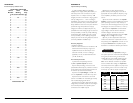
To properly set the amplifier for maximum clean
output, please refer to Appendix B (page 13) in this
manual.After using this procedure, you can then
adjust the “Input Sens.” level downward if this is
required to achieve the desired system balance.
Do not increase the “Input Sens.”setting for
any amplifier in the system beyond the maximum
level established during the procedure outlined in
Appendix B (page 13). Doing so will result in
audible distortion and possible speaker damage.
JL AUDIO 300/2 7
FUSE REQUIREMENTS
It is absolutely vital that the main power wire(s)
to the amplifier(s) in the system be fused within
18 inches (45 cm) of the positive battery post
connection.The fuse value at each power wire
should be high enough for all of the equipment
being run from that power wire. If only the
300/2 is being run from that power wire, we
recommend a 40A fuse be used.AGU (big glass
fuse) or MaxiFuse™ (big plastic-body fuse) types
are recommended.
No fuse is required or recommended directly
before the amplifier power connection. If one is
desired, we recommend the use of a 40A AGU fuse
or MaxiFuse™ type.
TURN-ON LEAD
The 300/2 uses a conventional +12V remote
turn-on lead, typically controlled by the source unit's
remote turn-on output.The amplifier will turn on
when +12V is present at its “Remote” input and
turn off when +12V is switched off. If a source unit
does not have a dedicated remote turn-on output,
the amplifier’s turn-on lead can be connected to
+12V via a switch that derives power from an
ignition-switched circuit.
The 300/2's “Remote” turn-on connector is
designed to accept 18 AWG – 8 AWG wire.
12 AWG is more than adequate for this purpose.
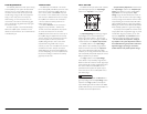
To connect the remote turn-on wire to the
amplifier, first back out the set screw on the top of
the amplifier, using the supplied hex wrench. Strip
1/2 inch (12mm) of wire and insert the bare wire
into the receptacle on the front panel of the
amplifier, seating it firmly so that no bare wire is
exposed.When using smaller wire, it may be
necessary to strip 1 inch of insulation from the wire
and fold the bare wire in half prior to insertion.
While holding the wire in the terminal, tighten the
set screw firmly,taking care not to strip the head of
the screw and making sure that the wire is firmly
gripped by the set screw.
6 JL AUDIO 300/2