


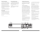
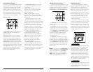

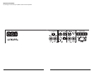

PREAMP OUTPUT SECTION
The 300/2 incorporates a flexible preamp output
section, so that additional amplifiers can be added to
the system.This pre-amp output can be configured
three different ways using the switch labeled
“Output Mode” in the “Preamp Output Section”.
1) “Full-Range”: The preamp output delivers
the same signal that is connected to the 300/2's
Amplifier Inputs.
2) “Low-Pass”: The preamp output delivers
the same signal that is connected to the 300/2's
Amplifier Inputs with Low-Pass filtering applied to
it at the “Filter Freq.” and “Filter Slope” selected
in the “Amplifier Filter” section. This mode can
be useful for feeding a subwoofer amplifier
when the 300/2 is being used to drive the
main speaker system.
3) “High-Pass”:The preamp output delivers
the same signal that is connected to the 300/2's
Amplifier Inputs with High-Pass filtering applied to
it at the “Filter Freq.” and “Filter Slope” selected
in the “Amplifier Filter” section. This mode can
be useful for feeding a second satellite amplifier
when the 300/2 is being used to drive the main
speaker system.
NOTE:The signal level of the “Preamp Output” is
affected by the setting of the“Input Voltage Range”
switch of the amplifier. See the “Input Voltage
Range” section (page 7) for details on “Input
Voltage” settings.The preamp output level is not
affected by the “Input Sens.”rotary control.
SPEAKER OUTPUTS
The 300/2 employs JL AUDIO's exclusive
Regulated, Intelligent Power Supply (R.I.P.S.) design.
This sophisticated power supply allows the
amplifier to produce its optimum power (300
watts) over a wide range of speaker impedances.
Unlike conventional amplifiers that require a
specific impedance to produce optimum power,
the R.I.P.S.-equipped 300/2 gives you the freedom
to use a variety of speaker configurations that
achieve final impedances between 1.5 – 4Ω
nominal per channel (without sacrificing power
output or sound quality).
The operation of the R.I.P.S. circuitry is entirely
automatic and adjusts itself every time the amplifier
is turned on according to the lowest impedance
present at the speaker outputs .There are no user
controls to configure.The system operates through
multiple stages of impedance optimization, choosing
the stage most appropriate to the actual impedance
of the speakers you connect to it.
If you connect a load higher than 4Ω nominal
per channel in stereo mode (or 8Ω in bridged
mode), power will drop by half with every
doubling of impedance above 4Ω stereo / 8Ω
mono. If you connect a load lower than 1.5Ω
nominal per channel in stereo mode (or 3Ω in
bridged mode, the amplifier protection circuitry
activates a “safe” mode which reduces amplifier
power to protect the circuitry from failure (the
yellow “Low Ω” LED lights to indicate that this
has happened). See page 10 for details.
Speaker loads below 1.5Ω nominal per channel
in stereo or 3Ω nominal in bridged mode are not
recommended and may cause the amplifier output
to distort excessively.
IMPORTANT
!
IMPORTANT
!
JL AUDIO 300/2 9
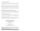
CROSSOVER CONTROLS
Crossovers are groups of individual electronic filters
which allow only certain frequency ranges to pass
through them by attenuating frequencies outside
the selected range.These filters allow the user to
specify what frequency range will be sent to the
each amplifier (or channels) in a system.This, in turn,
allows each speaker system to only reproduce a
range of frequencies it is well-suited for,resulting in
reduced distortion and improved fidelity.
Amp Filter Section:
1) “Filter Mode” Control:This switch allows you to
configure the filter into one of two filter types or
defeat it completely:
“Off”: Defeats the filter for that channel section
completely, allowing the full range of frequencies
present at the inputs to feed the amplifier.This is
useful for systems utilizing outboard crossovers or
requiring full-range reproduction from the 300/2.
“LP” (Low-Pass): Configures the filter to attenuate
frequencies above the selected filter frequency.
Useful for connection of subwoofer(s) to the 300/2.
“HP” (High-Pass): Configures the filter to attenuate
frequencies below the selected filter frequency.
Useful for connection of component speakers to
the 300/2 in a bi-amplified system.
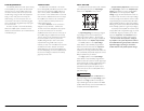
2) “Filter Slope” Control: This switch allows
you to select from two filter slopes for that
channel section.
“12dB”: Configures the filter to attenuate
frequencies above or below the selected filter
frequency at a rate of 12 dB per octave
(Butterworth alignment).
“24dB”: Configures the filter to attenuate
frequencies above or below the selected filter
frequency at a rate of 24 dB per octave (Linkwitz-
Riley alignment).
Depending on the speaker system and the
vehicle, different filter slopes may be required to
produce a smooth transition between the sound of
different speakers in the system. Experiment to find
the slope which best matches the acoustic
requirements of the system.The sharper “24dB”
setting will do a better job of protecting small
speakers with limited power handling.The shallower
“12dB” octave setting allows the rear speakers to
reproduce more low-frequency content.
3) “Freq. Range” Control: When thrown to
the right, this switch multiplies the cutoff
frequency selected by the rotary “Filter Freq.
(Hz)” control by a factor of 10. In the “x1”
position, the range of the rotary control is
50 - 500 Hz (as marked). In the “x10”
position, the range of the rotary control is
500 Hz - 5 kHz (5000 Hz).
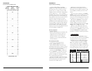
4) “Filter Freq. (Hz)”The filter frequency
markings surrounding this rotary control are for
reference purposes and are generally accurate to
within 1/3 octave or better. If you would like to
select the filter cutoff frequency with a higher level
of precision, consult the chart in Appendix A
(page 12) of this manual.
8 JL AUDIO 300/2