


2 | JL Audio - HD900/5 Owner’s Manual
PROTECT YOUR HEARING!
We value you as a long-term customer. For
that reason, we urge you to practice restraint in
the operation of this product so as not to damage
your hearing and that of others in your vehicle.
Studies have shown that continuous exposure to
high sound pressure levels can lead to permanent
(irreparable) hearing loss. This and all other
high-power amplifiers are capable of producing
such high sound pressure levels when connected
to a speaker system. Please limit your continuous
exposure to high volume levels.
While driving, operate your audio system in
a manner that still allows you to hear necessary
noises to operate your vehicle safely (horns,
sirens, etc.).
SERIAL NUMBER
In the event that your amplifier requires
service or is ever stolen, you will need to
have a record of the product’s serial number.
Please take the time to enter that number in
the space provided below. The serial number
can be found on the bottom panel of the
amplifier and on the amplifier packaging.
Serial Number:
INSTALLATION APPLICATIONS
This amplifier is designed for operation in
vehicles with 12V, negative-ground electrical
systems. Use of this product in vehicles with
positive ground and/or voltages other than 12V
may result in damage to the product and will void
the warranty.
This product is not certified or approved for
use in aircraft.
Do not attempt to “bridge” the outputs of this
amplifier with the outputs of a second amplifier,
including an identical one.
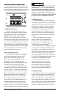
PLANNING YOUR INSTALLATION
It is important that you take the time to read
this manual and that you plan out your
installation carefully. The following are some
considerations that you must take into account
when planning your installation.
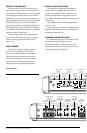
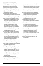
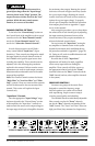
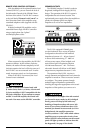
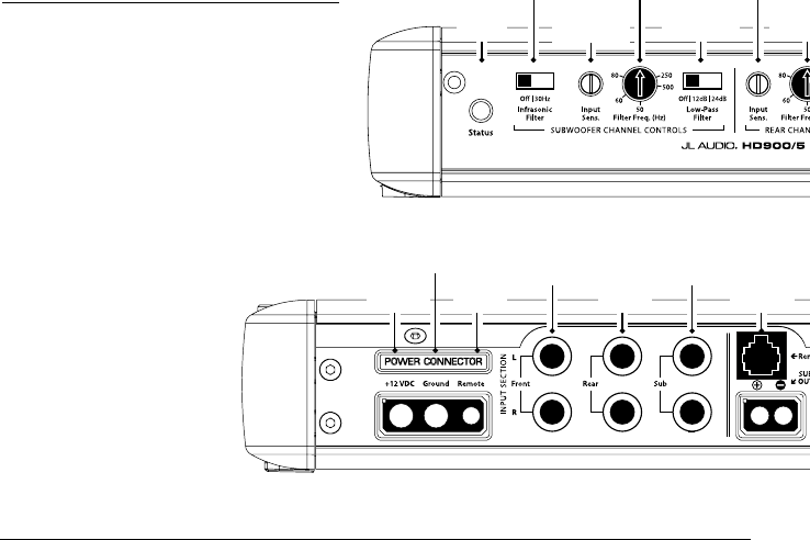
Filter Frequency
Selector
(pg. 11)
Filter Frequency
Selector
(pg. 10)
Input Voltage
Selection
(pg. 9)
Infrasonic Filter
Selector
(pg. 11)
Input Sensitivity
Control
(pg. 10)
Input Mode
Selection
(pg. 9)
Filter Slope
Selection
(pg. 11)
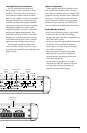
Filter Frequency
Selector
(pg. 11)
Input Sensitivity
Control
(pg. 10)
Filter Slope
Selection
(pg. 11)
Input Sensitivity
Control
(pg. 10)
Power Status
Indicator
(pg. 15)
Filter Slope
Selection
(pg. 11)
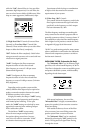
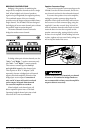
Left & Right
Input Jacks:
Subwoofer
(pg. 9)
Left & Right
Input Jacks:
Front Channels
(pg. 9)
Speaker Outputs
(pgs. 13-14)
Jack for
Remote Level
Control Knob
(pg. 13)
Left & Right
Input Jacks:
Rear Channels
(pg. 9)
Chassis Ground
Connector
(pgs. 6-7)
Remote Turn-On
Connector
(pgs. 6-7)
+12 V Power
Connector
(pgs. 6-7)