


9
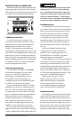
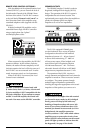
AMPLIFIER INPUTS
The HD900/5 has three separate input sections,
one for the “Front” left and right channels,
another for the “Rear” left and right channels
and one for the Subwoofer Channel. Each section
consists of a pair of RCA-type input jacks on
the Connection Panel of the amplifier and input
controls on the Control Panel of the amplifier: a
single “Input Voltage” switch, an “Input Mode”
switch and three individual “Input Sens.” rotary
controls (one in each channel section).
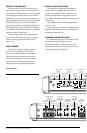
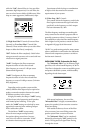
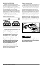
“INPUT MODE” SWITCH
The “Input Mode” switch is located under
the “General Setup” heading at the far right of
the control panel. This switch allows operation
of all five amplifier channels with only one pair
of input signals (2 ch.) or with independent front
and rear input signal pairs (4 ch.) or with discrete
front, rear and subwoofer signal pairs (6 ch.).
“6 Ch.” Input Mode
In this mode, you will connect separate pairs
of input cables to the “Front”, “Rear” and “Sub”
amplifier inputs, allowing you full channel
control from the source unit. If the source unit
only provides a mono (single) subwoofer output,
use a y-adaptor cable to feed both the “Left” and
“Right” subwoofer inputs of the HD900/5 with
the mono signal. Failure to do so will result in
reduced gain and possible distortion.
“4 Ch.” Input Mode
In this mode, you will connect separate
pairs of input cables to the “Front” and “Rear”
amplifier inputs and leave the “Sub” inputs
unused. The subwoofer channels will receive
signal from the sum of the signals at the “Front”
and “Rear” inputs so that front-to-rear fading of
the main channels does not significantly affect
the subwoofer level.
“2 Ch.” Input Mode
To operate all five channels of the HD900/5
with a single pair of stereo inputs, select the
“2 Ch.” position on the “Input Mode” switch
and connect a single pair of input cables to
the “Front” input jacks only. The “Rear”
and “Sub” input jacks will remain unused.
In this mode, the amplifier will route the
signals connected to the “Front” inputs to
the Front, Rear and Subwoofer channels.
Front-to-rear fading will not be available.
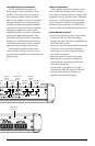
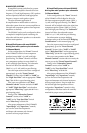
“Input Voltage” Switch
A wide range of signal input voltages can be
accommodated by each of the HD900/5’s differential-
balanced inputs (200mV – 8V RMS). This wide range
is split up into two sub-ranges, accessible via the
“Input Voltage” switch located next to the “Input
Mode” switch under the “General Setup” heading.
The “Low” position of the “Input Voltage”
switch selects an input sensitivity range between
200mV and 2V for all the amplifier channels. This
means that the “Input Sens.” rotary controls will
operate within that voltage window. If you are
using an aftermarket source unit, with preamp-
level outputs, this is most likely the position that
you will use (regardless of what voltage output
capability is claimed by the source unit).
The “High” position of the “Input Voltage”
switch selects an input sensitivity range between
800mV and 8V. This is for use with speaker-level
outputs from source units and small amplifiers
found in many OEM (factory-installed) systems.
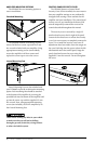
To use speaker-level sources, splice the speaker
output wires of the source unit or small amplifier
onto a pair of RCA plugs for each input pair or use
the JL Audio ECS Speaker Wire to RCA adaptor
(XB-CLRAIC2-SW). It is not necessary (or
advisable) to use “Line Output Converters” with
your HD900/5.