


12 JL Audio
13
APPENDIX B:
J2-360.2 Specifications
General Specifications:
Recommended Fuse Value: 40A
Recommended Fuse Type: AFS, AGU or MaxiFuse™ at
battery, 2 x 20A ATC fuses on amplifier chassis
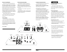
Input Sections:
No. of Inputs: One Stereo Pair
Low-Level Inputs: Single-ended with RCA jack inputs
Low-Level Input Range: 200mV - 4V RMS
High-Level Inputs: Single-ended with molded connector
High-Level Input Range: 2V - 10V RMS
Amplifier Section:
Amplifier Topology: Class A/B with Dual N-Channel
MOSFET output stage
Power Supply: PWM switching type, unregulated
Rated Power with less than 1% THD (14.4V supply):
Stereo, all channels driven:
110W RMS x 2 @ 4 ohms
135W RMS x 2 @ 3 ohms
180W RMS x 2 @ 2 ohms
Bridged, all channels driven:
220W RMS x 1 @ 8 ohms
270W RMS x 1 @ 6 ohms
360W RMS x 1 @ 4 ohms
Frequency Response: 10 Hz - 35 kHz +/- 0.5 dB
Crossover Sections:
Filter Type: 12dB/octave High-Pass or Low-Pass with
continuously variable cutoff frequency selection from
50 - 500 Hz. Defeatable.
Preamp Output:
2-Channel, pass-through with unity gain, RCA-type jacks.
Dimensions (LxWxH):
12.80" x 9.60" x 2.15" (325 mm x 244 mm x 55 mm)
APPENDIX A:
Input Sensitivity Level Setting
Following the directions below will allow the
installer to adjust the input sensitivity of each
amplifier channel pair simply and easily in just a
few minutes using equipment which is commonly
available in installation bays.
Necessary Equipment
• Digital AC Voltmeter
• CD with a sine-wave test tone recorded at
0 dB reference level in the frequency range
to be amplified for that set of channels
(50 Hz for subwoofer channels, 1 kHz for a
midrange application). Do not use attenuated
test tones (-10 dB, -20 dB, etc.).
The Nine-Step Procedure
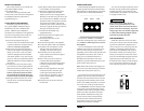
1) Disconnect the speaker(s) from the
amplifier’s speaker output connectors.
2) Turn off all processing (bass/treble, loudness,
EQ, etc.) on the source unit, processors (if
used) and amplifier. Set fader control to center
position and subwoofer level control to 3/4 of
maximum. If connected, set the amplifier’s
Remote Bass Control at maximum (full
clockwise).
3) Turn the “Input Sens.” control all the
way down.
4) Set the source unit volume to 3/4 of full
volume. This will allow for reasonable gain
overlap with moderate clipping at full volume.
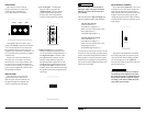
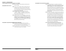
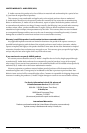
5) Using the chart on this page, determine the target
voltage for input sensitivity adjustment according
to the nominal impedance of the speaker system
connected to the amplifier outputs.
6) Verify that you have disconnected
the speakers before proceeding. Play
a track with an appropriate sine wave
(within the frequency range to be
amplified) at 3/4 source unit volume.
7) Connect the AC voltmeter to the speaker output
connectors of the amplifier. Make sure you test
the voltage at the correct connectors (+ and –).
8) Increase the “Input Sens.” control until the
target voltage is observed with the voltmeter.
9) Once you have adjusted the amplifier to
its maximum low-distortion output level,
reconnect the speaker(s). The “Input Sens.”
controls can now be adjusted downward if the
amplifier requires attenuation to achieve the
desired system balance.
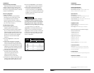
IMPORTANT
!
Do not increase any “Input Sens.” setting for
any amplifier channel or channel pair in the
system beyond the maximum level established
during this procedure. Doing so will result in
audible distortion and possible speaker damage.
It will be necessary to re-adjust the
“Input Sens.” for the affected channels if any
equalizer boost is activated after setting the
“Input Sens.” with this procedure. This applies
to any EQ boost circuit, including source unit
tone controls or EQ circuits. EQ cuts will not
require re-adjustment.
Due to ongoing product development, all specifications are subject to
change without notice.
Nom.
Impedance
Target AC Voltage
Stereo Bridged
8
21 V 42 V
6
21 V 40 V
4
21 V 38 V
3
20 V not recommended
2
19 V not recommended