


4 JL Audio®
5
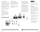
POWER CONNECTIONS
Before installing the amplifier, disconnect the
negative (ground) wire from the vehicle’s battery.
This will prevent accidental damage to the system,
the vehicle and your person during installation.
Made in China
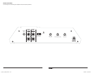
Speaker Output (Mono)FUSES + 12VDC
15A15A15A15A
RemoteGround
The J2-500.1’s “+12 VDC” (positive) and
“Ground” (ground) connections are designed to
accept 4 AWG power wire. 4 AWG is a minimum
power wire size for this amplifier.
If you are installing the J2-500.1 with other
amplifiers and wish to use a single main power
wire, use 2 AWG or 1/0 AWG main power wire
(depending on the overall current demands of
all the amplifiers in the system). This 2 AWG
or 1/0 AWG power wire should terminate into
a distribution block mounted as close to the
amplifiers as possible and should connect to the
J2-500.1 with 4 AWG power wire.
Note: that smaller AWG numbers mean bigger
wire and vice-versa (1/0 AWG is the largest,
2 AWG is smaller, then 4 AWG, then
8 AWG, etc.).
To connect the power and ground wires to the
amplifier, strip 1/2-inch (12 mm) of insulation
from each wire and insert the bare wire into the
the appropriate terminal block positions on the
J2-500.1. Use a Phillips screwdriver to secure the
wire via the screw on the top of each terminal.
The “Ground” connection should be made
using 4 AWG wire and should be kept as short
as possible, while accessing a solid piece of sheet
metal in the vehicle. The surface of the sheet
metal should be sanded at the contact point
to create a clean, metal-to-metal connection
between the chassis and the termination of
the ground wire. The use of a star washer to
lock down the connection is advisable.
Any wires run through metal barriers (such as
firewalls), must be protected with a high quality
insulating grommet to prevent damage to the
insulation of the wire. Failure to do so may result
in a dangerous short circuit.
Many vehicles employ small (10 AWG -
6 AWG) wire to ground the battery to the
vehicle chassis and to connect the alternator’s
positive connection to the battery. To prevent
voltage drops, these wires should be upgraded
to 4 AWG (or larger) when installing a J2-500.1.
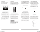
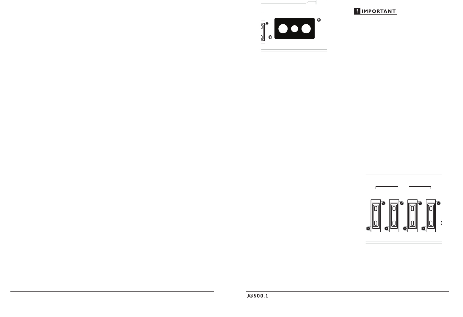
FUSE REQUIREMENTS
While the J2-500.1 has four 15A ATC fuses
on its power connection panel, these do nothing
to protect the vehicle from a dangerous short
circuit in the power wire. They only protect the
amplifier. It is absolutely vital that the main
power lead to the amplifier(s) in the system be
fused within 18 inches (45 cm) of the positive
battery post connection. The fuse value at each
power wire should be high enough for all of the
equipment being run from that power wire.
If only the J2-500.1 is being run from that power
wire, we recommend a 60A fuse be used. AFS or
MAXI-type fuses are recommended.
Made in China
Speaker Output (Mono)FUSES + 12VDC
15A15A15A15A
RemoteGround
PRODUCT DESCRIPTION
The JL Audio J2-500.1 is a monoblock
subwoofer amplifier utilizing Class B
technology. Its frequency response is limited
to the range below 125 Hz. It is not designed
for driving midrange speakers or tweeters.
It has been optimized for low-frequency
amplification. For detailed specifications,
please refer to Appendix B (page 11).
TYPICAL INSTALLATION SEQUENCE
The following represents the sequence
for a typical amplifier installation, using an
aftermarket source unit or OEM Interface
product. Additional steps and different
procedures may be required in some applications.
If you have any questions, please contact your
authorized JL Audio dealer for assistance.
1) Disconnect the negative battery post
connection and secure the disconnected cable
to prevent accidental re-connection during
installation. This step is not optional!
2) Run power wire (minimum 4 AWG)
from the battery location to the amplifier
mounting location, taking care to
route it in such a way that it will not be
damaged and will not interfere with
vehicle operation. Use 2 AWG or 1/0
AWG power wire if additional amplifiers
are being installed with the J2-500.1.
3) Connect power wire to the positive battery
post. Fuse the wire with an appropriate fuse
block (and connectors) within 18 inches (45
cm) wire length of the positive battery post.
This fuse is essential to protect the vehicle.
Do not install the fuse until the power wire
has been connected to the amplifier.
4) Run signal cables (RCA cables) and remote
turn-on wire from the source unit to the
amplifier mounting location.
5)
Run speaker wire from the speaker systems
to the amplifier mounting location.
6)
Find a good, solid metal grounding point
close to the amplifier and connect the negative
power wire to it using appropriate hardware.
Use minimum 4 AWG power wire, no longer
than 36 inches (90 cm) from the amplifier to
the ground connection point. In some vehicles,
it may be necessary to upgrade the battery
ground wire. (See page 5 for important notice).
7)
Securely mount the amplifier using
appropriate hardware.
8)
Connect the positive and negative power
wires to the amplifier.
9)
Connect the remote turn-on wire
to the amplifier.
10)
Connect the RCA input cables
to the amplifier.
11)
Connect the speaker wires to the amplifier.
12)
Carefully review the amplifier’s control
settings to make sure that they are set according
to the needs of the system.
13)
Install power wire fuse (60A for a single J2-500.1)
and reconnect the negative battery post terminal.
14)
Turn on the source unit at a low level
to double-check that the amplifier is configured
correctly. Resist the temptation to crank it up
until you have verified the control settings.
15)
Make necessary adjustments to the input
sensitivity controls to obtain the right
overall output and the desired balance
in the system. See Appendix A (page 10)
for the recommended input sensitivity
setting method.
16)
Enjoy the fruits of your labor with your
favorite music.
J2_500_1_MAN_CH.indd 4-5 4/22/09 11:24:41 AM