


12 JL Audio®
13
“My amplifier turns on, but there is no output”
Check the input signal using an AC voltmeter to measure the
voltage from the source unit while an appropriate test tone is
played through the source unit (disconnect the input cables
from the amplifier prior to this test). The frequency used
should be in the range that is to be amplified by the amplifier
(example: 50 Hz for a sub bass application or 1 kHz for a full
range / high-pass application). A steady, sufficient voltage
(between 0.2 and 8.0-volts) should be present at the output of
the signal cables.
Check the output of the amplifier. Using the procedure explained in
the previous check item (after plugging the input cables back
into the amplifier) test for output at the speaker outputs of
the amplifier. Unless you enjoy test tones at high levels, it is
a good idea to remove the speaker wires from the amplifier
while doing this. Turn the volume up approximately half
way. 5V or more should be measured at the speaker outputs.
This output level can vary greatly between amplifiers but it
should not be in the millivolt range with the source unit at
half volume. If you are reading sufficient voltage, check your
speaker connections as explained below.
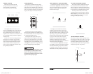
Check to ensure that the speaker wires are making a good
connection with the metal inside the terminal block. The
speaker wire connectors are designed to accept up to 8 AWG
wire. Make sure to strip the wire to allow for a sufficient
connection with the metal inside the terminal block.
“How do I properly set the input sensitivity on my amplifier”
Please refer to Appendix A (page 10) to set the input sensitivity for
maximum, low-distortion output.
“My amplifier doesn’t turn on”
Check the fuse, not just visually, but with a continuity meter. It is
possible for a fuse to have poor internal connections that
cannot be found by visual inspection. It is best to take the
fuse out of the holder for testing. If no problem is found with
the fuse, inspect the fuse-holder.
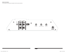
Check the integrity of the connections made to each of the
“+12VDC”, “Ground”, and “Remote” terminals. Ensure
that no wire insulation is pinched by the terminal set screw
and that each connection is tight.
Check to make sure there is +12V at the “Remote” connection of the
amplifier. In some cases, the turn-on lead from the source unit
is insufficient to turn on multiple devices and the use of a relay
is required. To test for this problem, jump the “+12VDC” wire
to the “Remote” terminal to see if the amplifier turns on. If this
does not work, proceed to the next step.
“My amplifier’s output fluctuates when I tap on it or hit a bump”
Check the connections to the amplifier. Make sure that the
insulation for all wires has been stripped back far enough to
allow a good contact area inside the terminal block.
Check the input connectors to ensure that they all are making good
contact with the input jacks on the amplifier.
APPENDIX C: TROUBLESHOOTING
J2_500_1_MAN_CH.indd 12-13 4/22/09 11:24:47 AM