


Continued on Next Page
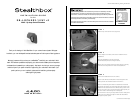
SB-J-GCHER3/10W1v2_INSTR_SKU#011235
SB-J-GCHER3/10W1v2_INSTR_SKU#011235
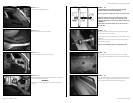
STEP 15
If needed, with the 3/8” drill bit and drill. Drill the metal panel
were it was marked from STEP 3.
*WARNING*
The metal behind this side panel is the outer metal of the
vehicle.
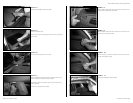
STEP 14
Remove the plastic panel from the vehicle.
STEP 13
Remove the right rear door’s sill plate.
STEP 12
Remove the d-pillar plastic cover.
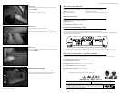
VEHICLE SHEET METAL
SOCKET CUP SET SCREW
HEX BOLT
LOCK WASHER
STEALTHBOX WALL
COUPLERS
HEX NUT
LOCK WASHER
FLAT WASHER
SOCKET CUP SET SCREW
FLAT WASHER
Page 3 • JL Audio, Inc 2007
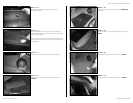
STEP 17
Place the hex bolt assembly through the drilled hole, from
the back side of the metal panel.
Apply a wrench onto the coupler that is in front of the metal
side panel.
Apply a 9/16-inch open end wrench to the hex bolt that is
behind the metal panel.
Secure the mounting assembly to the metal side panel.
STEP 19
Place the plastic side panel back into place. Guide the socket
cup set screw through the drilled hole. Only the socket cup
set screw should protrude through the plastic panel.
STEP 18
From the back side of the plastic side panel, cut out and
remove the sound deadening that is around the drilled hole.
STEP 16
The illustration to the left shows how all the supplied
hardware makes up the mounting assembly.
Place a lock washer and then flat washer onto the hex bolt.
Place both coupler nuts onto one socket cup set screw.
Make sure that there is enough room inside one of the
couplers to allow the hex bolt to be properly inserted, look
to STEP 17.
Fully thread in the second socket cup set screw into the
other coupler.