


Continued on Next Page
SB-SMRT-4-2/8W3V3 INSTR_SKU# 011288
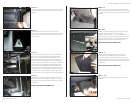
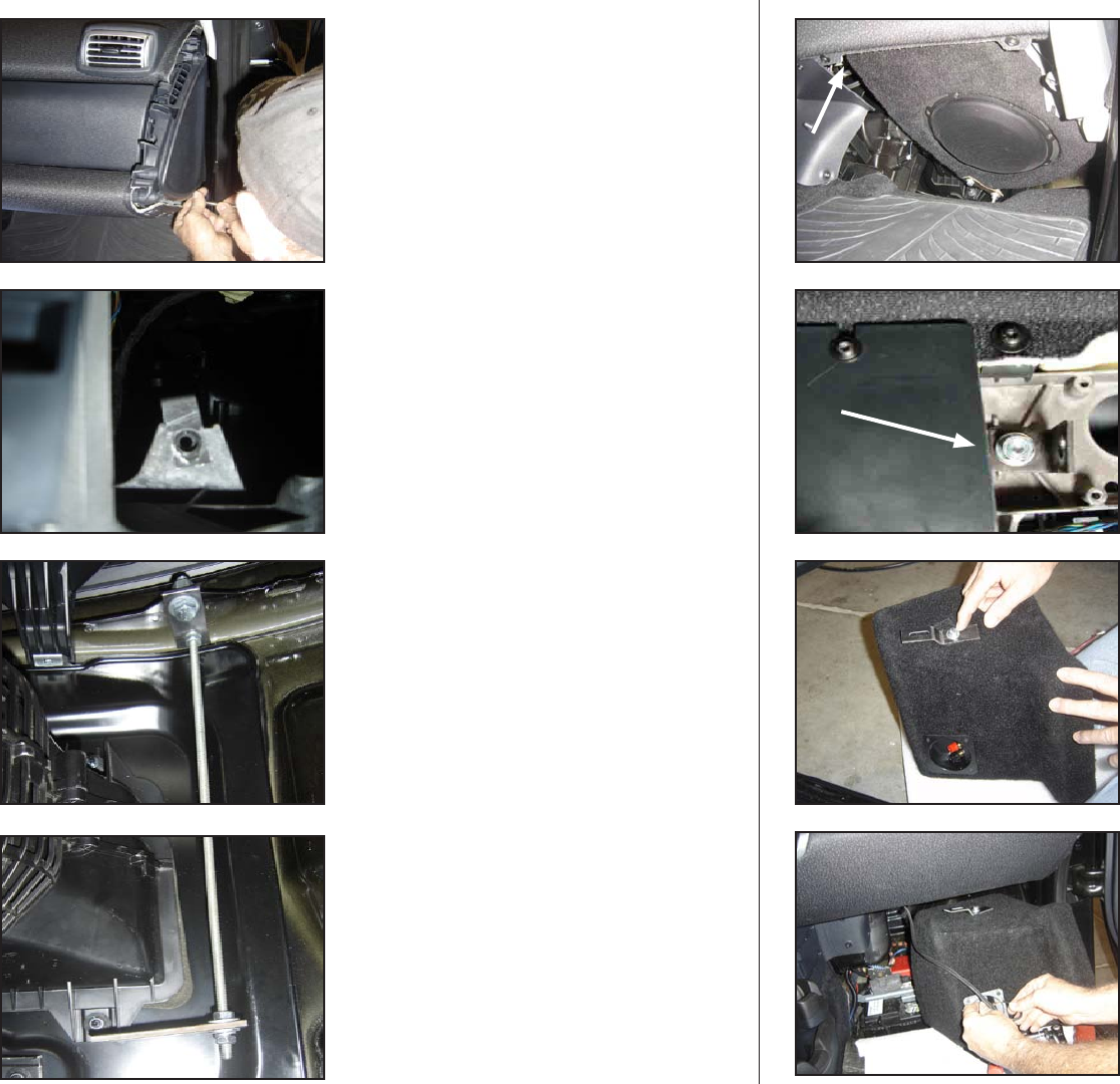
S T E P 7
On the Bottom end of the 1/4-20 All Threaded Rod, install
the Bottom Bracket as shown (approximately 1- 1 1/4” from
the bottom), using included 1/4-20 Nuts, Washers and, Split
Lock Washer.
DO NOT TIGHTEN THIS ASSEMBLY YET!
S T E P 6
Looking from under the dash, near the front of the vehicle,
there is a flange just under the top of the dash that has a
factory hole . Assemble the included Top Bracket and,
1/4-20 All Threaded Rod by putting on a 1/4-20 Nut and,
Split Lockwasher then threading the rod into the bracket so
that just a few threads come out on the top side. Tighten the
1/4-20 Nut and, Split Lockwasher to the Top Bracket. Once
the Top Bracket/ All Threaded Rod have been assembled,
bolt the other end of the Top Bracket to the flange using the
included 3/8-16 x 1” Hex Head Bolt, Nut, Washers and, Split
Lock Washer then rotate the Bracket so that it rests on the
top of AC system as shown, tighten down all of this hadware.
S T E P 5
Looking into the end of the dash, you will notice the
aluminum extrusion that is the frame of the dash. There is an
exposed slot, slide the included 1/4-20 Speed Clip over this
notch as shown.
S T E P 4
Once the trim piece is removed, there are three Torx screws
that hold the dash end piece in place, remove those and the
end piece.
Page 2 • JL Audio, Inc 2009
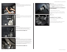
D E T A I L
Install the included right angle bracket as shown through
the slot in the dash extrusion using the included
3/8-20 Nut, Washers, 3/8-16 x 1 1/2” Hex Head Bolt, and,
Split Lockwasher. the end with the hole closest to the bend
is against the dash extrusion. Slide the bracket all the way
towards the center of the vehicle, oriented as shown.
DO NOT TIGHTEN THIS ASSEMBLY YET!
S T E P 1 0
Attach the wire from the amplifier to the terminals on the
Stealthbox®
S T E P 9
Remove the woofer from the enclosure. Mount the
Elevated Bracket to the Stealthbox® as shown with the
slotted end exposed and pointing towards the top of the
enclosure, using the included 1/4-20 x 1” Hex Head Bolt, Split
Lockwasher and Washer. Snug this hardware down so that it
isn’t loose but,
DO NOT TIGHTEN THIS ASSEMBLY YET!
S T E P 8
This picture is only to illustrate where the DETAIL below is
located, the enclosure and, woofer have NOT been mounted
yet. Where the arrow is pointing is where the DETAIL below
is located.