


Specifications:
Enclosure Type: Acoustic Suspension (Sealed)
Driver Type: One JL AUDIO 10W3v2-D2 Subwoofer
Nominal Impedance: 4Ω
Cont. Power Handling: 300 Watts
JLAudio recommends using a high quality amplifier such as the JLAudio 250/1. The diagram below shows the recommended
crossover,infrasonic filter and equalizer settings for the 250/1 when being used to power the the Audio Stealthbox®.
Included Hardware:
(2) 1/4" Flat Washer
(2) 1/4" Lock Washer
(1) 1/4” U-Nut
(2) 1/4” x 1” Bolt
(1) L-Bracket
10369 N. Commerce Pkwy, Miramar, Florida 33025-392 Phone: 954.443.1100 Fax: 954.443.1111
JL AUDIO 250/1
monoblock subwoofer amplifier
Amplifier Input Section
Input Sens.
Input Voltage
Low/High
Left Ch.
Right Ch.
Signal Sensing
Off/On
Output Mode
Full-Range/Low-Pass/High-Pass
Left Ch.
Right Ch.
Amp LP Filter
Mode/Slope
Off/12dB/24dB
Filter Freq. (Hz)
Bass Control
LF Boost (dB)
Off/30Hz
Infrasonic Filter
+1
+13
+3
+7
+10
Preamp Output Section
+12VDC Ground Remote
The JLAudio 250/1 is a very versatile audio component. Please consult the owner’s manual for detailed information
about installing and tuning this amplifier.
SB-T-SEQ/10W3v2-D2, JL AUDIO, Inc 2002
Sheet SKU#011111 Revision 10/30/02Page 3
www.jlaudio.com
Mid/High Frequency Driver Information:
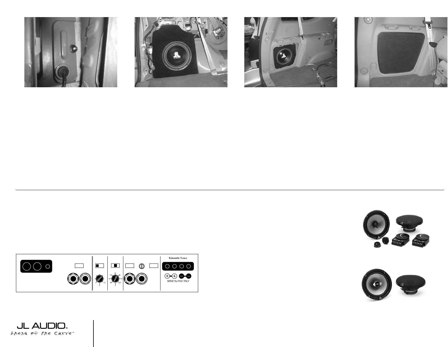
CONGRATULATIONS!
INSTALL COMPLETE.
VR650-CSi
(1) 3/8” Split Lock Washer
(1) 3/8” x 1-1/4” Fender Washer
(1) 3/8” x 2 1/4” Socket Cup Set Screw
(1) 3/8” Hex Nut
(1) Grille
(1) 3” x 3”Wax Square
TR650-CXi
Front Applicable JL Audio Products:
TR650-CSi & CXi
VR650-CSi & CXi
Rear Applicable JL Audio Products:
TR650-CXi,VR650-CXi
➔➔
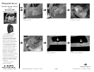
STEP 15:
Adjusting the Socket Set Cup
Screw so that the proper length is exposed
(the exposed end of the rod is slotted to
accept a flat-blade screw driver to be used
when adjusting the rod’s position). Place the
3/8” flat washer, 3/8” lock washer and
3/8”bolt, in that order, on the threaded rod.
Do not fully tighten.
➔
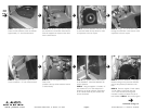
STEP 17:
Fully tighten the bolt on the top of
the enclosure and the nut on the threaded
rod on the bottom of the enclosure to secure
the enclosure.
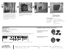
STEP 18:
Reinstall the factory side panel.
STEP 19:
Attach the supplied grill to the
factory side panel.
Cont.
From
Page 2
➔