


14 | JL Audio - XD700/5 Owner’s Manual
APPENDIX A:
Input Sensitivity Level Setting
Following the directions below will allow the
installer to adjust the input sensitivity of each
amplifier channel pair simply and easily in just a
few minutes using equipment which is commonly
available in installation bays.
Necessary Equipment
• Digital AC Voltmeter
• CD with a sine-wave test tone recorded at
0 dB reference level in the frequency range
to be amplified for that set of channels
(50 Hz for subwoofer channels, 1 kHz for a
midrange application). Do not use attenuated
test tones (-10 dB, -20 dB, etc.).
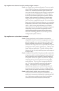
The Nine-Step Procedure
1) Disconnect the speaker(s) from the
amplifier’s speaker output connectors.
2) Turn off all processing (bass/treble, loudness,
EQ, etc.) on the source unit, processors (if
used) and amplifier. Set fader control to center
position and subwoofer level control to 3/4 of
maximum (if used to feed the XD700/5).
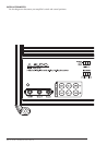
3) Turn all three “Input Sens.” controls all the
way down.
4) Set the source unit volume to 3/4 of full
volume. This will allow for reasonable gain
overlap with moderate clipping at full volume.
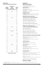
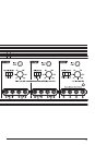
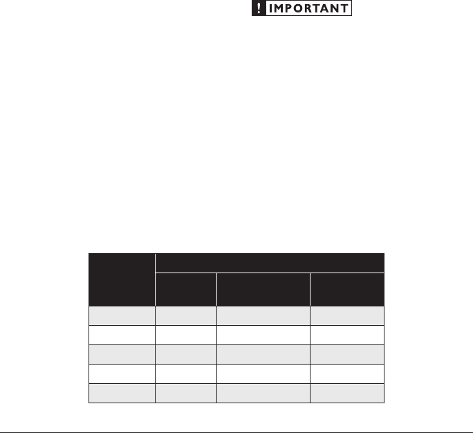
5) Using the chart on this page, determine the target
voltage for input sensitivity adjustment according
to the nominal impedance of the speaker system
connected to the amplifier outputs.
6) Verify that you have disconnected the speakers
before proceeding. Play a track with an
appropriate sine wave (within the frequency
range to be amplified by the channel you are
adjusting) at 3/4 source unit volume.
7) Connect the AC voltmeter to the speaker output
connectors of the amplifier. If the channel
pair is operating in stereo, it is only necessary
to measure one channel. If bridged, make sure
you test the voltage at the correct connectors
(L+ and R–).
8) Increase the “Input Sens.” control until the
target voltage is observed with the voltmeter.
9) Once you have adjusted each channel sectio of
the XD700/5 to its maximum low-distortion
output level, reconnect the speaker(s).
The “Input Sens.” controls can now be
adjusted downward if the amplifier requires
attenuation to achieve the desired system
balance.
Do not increase any “Input Sens.” setting for
any amplifier channel or channel pair in the
system beyond the maximum level established
during this procedure. Doing so will result in
audible distortion and possible speaker damage.
It will be necessary to readjust the
“Input Sens.” for the affected channels if any
equalizer boost is activated after setting the
“Input Sens.” with this procedure. This applies
to any EQ boost circuit, including source unit
tone controls or EQ circuits. EQ cuts will not
require re-adjustment.
Nom.
Impedance
Target AC Voltage
Main CH
(Stereo)
Main CH
(Bridged)
Subwoofer
CH
8
17.4 V 34.8 V 24.5 V
6
17.4 V 32.8 V 24.5 V
4
17.4 V 28.2 V 24.5 V
3
16.4 V not recommended 26.9 V
2
14.1 V not recommended 26.8 V