


3
PLANNING YOUR INSTALLATION
It is important that you take the time to read
this manual and that you plan out your
installation carefully. The following are some
considerations that you must take into account
when planning your installation.
Cooling Efficiency Considerations:
The outer shell of your JL Audio amplifier is
designed to remove heat from the amplifier
circuitry. For optimum cooling performance, this
outer shell should be exposed to as large a volume
of air as possible. Enclosing the amplifier in a
small, poorly ventilated chamber can lead to
excessive heat build-up and degraded
performance. If an installation calls for an
enclosure around the amplifier, we recommend
that this enclosure be ventilated with the aid
of a fan. In normal applications, fan-cooling
is not necessary.
Mounting the amplifier upside down is
strongly discouraged. If mounting the amplifier
under a seat, make sure there is at least 1 inch
(2.5 cm) of space above the amplifier’s outer
shell to permit proper cooling.
Safety Considerations:
Your amplifier needs to be installed in a dry,
well-ventilated environment and in a manner
which does not interfere with your vehicle’s safety
equipment (air bags, seat belt systems, ABS brake
systems, etc.). You should also take the time to
securely mount the amplifier so that it does not
come loose in the event of a collision or a sudden
jolt to the vehicle.
Stupid Mistakes to Avoid
• Check before drilling any holes in your vehicle
to make sure that you will not be drilling
through a gas tank, brake line, wiring harness or
other vital vehicle system.
• Do not run system wiring outside or underneath
the vehicle. This is an extremely dangerous
practice which can result in severe damage to
your vehicle and person.
• Protect all system wires from sharp metal
edges and wear by carefully routing them,
tying them down and using grommets and
loom where appropriate.
• Do not mount the amplifier in the engine
compartment, under the vehicle, on the roof
or in any other area that will expose the
amplifier circuitry to the elements.
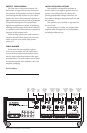
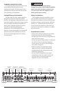
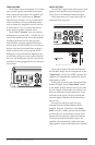
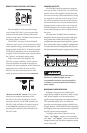
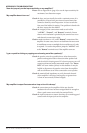
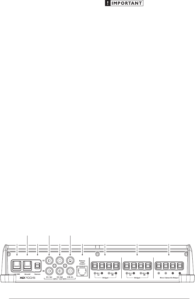
Remote Turn-On
Connector
(pg. 6)
Chassis Ground
Connector
(pg. 5)
Channels 1 & 2
Preamp Input Jacks
(pg. 7)
Subwoofer Ch.
Preamp Input Jacks
(pg. 7)
+12 V Power
Connector
(pg. 5)
Mono
Subwoofer Outputs
(pg. 10)
Channels 3 & 4
Speaker Outputs
(pg. 10)
Channels 1 & 2
Speaker Outputs
(pg. 10)
Jack for
Remote Level
Control Knob
(pg. 9)
Channels 3 & 4
Preamp Input Jacks
(pg. 7)