


2
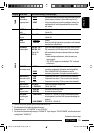
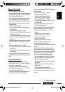
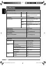
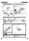
When using the optional stay / ‡¡◊ËÕ„™Èµ—«¬÷¥·∫∫‡≈◊Õ°‰¥È
Note : When installing the unit on the mounting bracket, make sure to use the 8 mm-long screws. If longer screws are
used, they could damage the unit.
À¡“¬‡Àµ :
‡¡◊ËÕµ‘¥µ—Èß™ÿ¥ª√–°Õ∫≈ß„π·∑Ëπ√Õß√—∫‰«È „ÀÈ„™È
°√Ÿ¬“«¢π“¥
8
¡¡.
∂È“„™È
°√Ÿ¬“«°«Ë“π’ÈÕ“®∑”„ÀÈ™ÿ¥ª√–°Õ∫‡
’¬À“¬‰¥ô
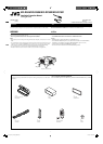
Bracket *
6
·∑Ëπ√Õß√—∫ *
6
Pocket
°–‡ª“–
Flat head screws (M5 × 8 mm) *
6
°√ŸÀ—«‡√’¬∫ (M5 × 8 ¡¡.) *
6
Screw*
6
°√Ÿ*
6
Stay *
6
µ—«¬÷¥*
6
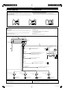
Fire wall
ºπ—ß°—π‰ø
Dashboard
·ºßÀπÈ“ªí∑¡á
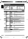
Install the unit at an angle of less than 30˚.
µ‘¥µ—Èß™ÿ¥ª√–°Õ∫∑’Ë¡ÿ¡µË”°«Ë“ 30˚ Õß»“
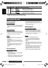
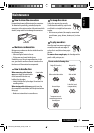
Removing the unit
Before removing the unit, release the rear section.
Insert the two handles, then pull them as
illustrated so that the unit can be removed.
„˧—π∫—ߧ—∫ 2 Õ —π≈ß„π√ËÕß”À√—∫„™Èæ—π≈«¥ ¥—ß¿“æ ®“°π—Èπ
„Àȇ≈◊ËÕπ™ÿ¥ª√–°Õ∫ÕÕ° „π¢≥–∑’˧ËÕ¬ Ê ¥÷ߧ—π∫—ߧ—∫∑—Èß Õß
Õ—πÕÕ°®“°°—π
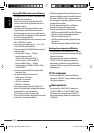
Do the required electrical connections.
µËÕ“¬‰øµ“¡∑’Ë°”À𥉫È∑—ÈßÀ¡¥
Bend the appropriate tabs to hold the
sleeve firmly in place.
ßÕ·ºËπ‡æ◊ËÕ¬÷¥ª≈Õ°„ÀȵËÕ°—π‡¢È“∑’Ë
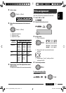
INSTALLATION (IN-DASH MOUNTING)
The following illustration shows a typical installation. If you have any questions or require information
regarding installation kits, consult your JVC car audio dealer or a company supplying kits.
• If you are not sure how to install this unit correctly, have it installed by a qualified technician.
When installing the unit without using the sleeve / ‡¡◊ËÕµ‘¥µ—Èß™ÿ¥ª√–°Õ∫‚¥¬‰¡Ë„™Èª≈Õ°ÀÿÈ¡
In a Toyota car for example, first remove the car radio and install the unit in its place.
µ—«Õ¬Ë“߇™Ëπ „π√∂¬πµÏ‚µ‚¬µÈ“ „ÀÈ∂Õ¥«‘∑¬ÿµ‘¥√∂¬πµÏÕÕ°°ËÕπ ·≈ô«®÷ßµ‘¥µíô߇§√◊ËÕßπ’ô‡¢ô“·∑π∑’Ë
°“√µ‘¥µ—Èß
(°“√ª√–°Õ∫·ºßÀπÈ“ªí∑¡Ï‡¢È“)
¿“æµ—«Õ¬Ë“ßµËÕ‰ªπ’È·¥ß∂÷ß°“√µ‘¥µ—Èß·∫∫∑—Ë«‰ª À“°§ÿ≥¡’ªí≠À“À√◊ÕµÈÕß°“√¢ÈÕ¡Ÿ≈‡°’ˬ«°—∫™ÿ¥µ‘¥µ—Èß °√ÿ≥“ª√÷°…“°—∫ºŸÈ¢“¬‡§√◊ËÕ߇’
¬ß√∂¬πµÏ
JVC ¢Õß∑Ë“πÀ√◊Õ∫√‘…—
• ™ÿ¥ª√–°Õ∫ ∂È“§ÿ≥‰¡Ë·πË„®«Ë“µ‘¥µ—Èß™ÿ¥ª√–°Õ∫π’È∂Ÿ°µÈÕßÀ√◊Õ‰¡Ë „ÀÈÀ“™Ë“ߺŸÈ‡™’ˬ«™“≠‡ªìπºŸÈµ‘¥µ—Èß
°“√∂Õ¥™ÿ¥ª√–°Õ∫
°ËÕπ®–∂Õ¥™ÿ¥ª√–°Õ∫ „ÀȪ≈¥ÀπÈ“µ—¥Ë«π∑È“¬°ËÕπ
Flat head screws (M5 × 8 mm) *
6
°√ŸÀ—«‡√’¬∫ (M5 × 8 ¡¡.) *
6
Bracket *
6
·∑Ëπ√Õß√—∫ *
6
*
1
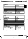
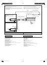
When you stand the unit, be careful not to damage the fuse on the rear.
*
2
Rubber cushion—Not supplied for this unit.
*
3
Mounting bolt (M4 × 5 mm; M5 × 12.5 mm)—Not supplied for this unit.
*
4
Washer (ø5)—Not supplied for this unit.
*
5
Lock nut (M5)—Not supplied for this unit.
*
6
Not supplied for this unit.
*
1
‡¡◊ËÕ§ÿ≥µ—Èß™ÿ¥ª√–°Õ∫¢÷Èπ √–«—ßլ˓∑”„ÀÈøî«Ï∫√‘‡«≥Ë«π∑È“¬‡’¬À“¬
*
2
¬“ß°—π°√–·∑°—‰¡Ë‰¥È„ÀÈ¡“°—∫™ÿ¥ª√–°Õ∫π’È
*
3
≈—°µ‘¥ (M4 × 5 ¡¡.; M5 × 12.5 ¡¡.)—‰¡Ë‰¥È„ÀÈ¡“°—∫™ÿ¥ª√–°Õ∫π’È
*
4
ª√–‡°Áπ«ß·À«π
(ø5)—‰¡Ë‰¥È„ÀÈ¡“°—∫™ÿ¥ª√–°Õ∫π’È
*
5
πÕµ≈ÁÕ§ (M5)—‰¡Ë‰¥È„ÀÈ¡“°—∫™ÿ¥ª√–°Õ∫π’È
*
6
‰¡Ë‰¥È„ÀÈ¡“°—∫™ÿ¥ª√–°Õ∫π’È
TH Install1-2_KD-R506_009B.indd 2TH Install1-2_KD-R506_009B.indd 2 4/27/09 6:30:56 PM4/27/09 6:30:56 PM