


3
ENGLISH
‰∑¬
A
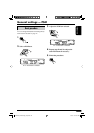
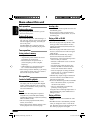
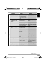
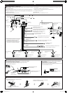
Typical Connections / °“√‡™◊ËÕ¡µËÕ·∫∫ª°µ
Before connecting: Check the wiring in the vehicle carefully. Incorrect connection may cause
serious damage to this unit.
The leads of the power cord and those of the connector from the car body may be different in
color.
1 Connect the colored leads of the power cord in the order specified in the illustration below.
2 Connect the antenna cord.
3 Finally connect the wiring harness to the unit.
*
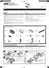
1
Not included for this unit.
*
1
‰¡Ë‰¥È„ÀÈ¡“°—∫™ÿ¥ª√–°Õ∫π
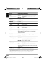
Ignition switch
«‘∑™Ï®ÿ¥√–‡∫‘¥
CD changer jack
(see diagram )
™ËÕ߇’¬∫µËÕ¢Õ߇§√◊ËÕ߇≈Ëπ´’¥
CD (¥Ÿ·ºπ¿Ÿ¡ )
Rear ground
terminal
®ÿ¥‡™◊ËÕ¡µËÕ“¬¥‘π¥È“πÀ≈—ß
15 A fuse
ø‘«Ï¢π“¥ 15 A
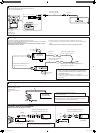
Black
’¥”
To metallic body or chassis of the car
µËÕ°—∫‚§√ß‚≈À–À√◊Õ‡™´‘¢Õß√∂¬πµú
Yellow *
2
’‡À≈◊Õß *
2
To a live terminal in the fuse block connecting to the car battery
(bypassing the ignition switch) (constant 12 V)
µµËÕ°—∫¢—È«∑’Ë¡’°√–·‰øøÈ“„π·ºßø‘«Ï ´÷ËßµËÕ°—∫·∫µ‡µÕ√’Ë√∂¬πµ
(‚¥¬‰¡ËµÈÕß„™È«‘∑™Ï®ÿ¥√–‡∫‘¥) (12 ‚«≈∑ϧß∑’Ë)
Red
’·¥ß
To an accessory terminal in the fuse block
µËÕ°—∫¢—È«Ë«πª√–°Õ∫„π·ºßø‘«
Blue
»’øÈ“
To the automatic antenna if any (250 mA max.)
‡“Õ“°“»‰øøÈ“Õ—µ‚π¡—µ‘ À“°¡’ (¢π“¥Ÿß¸¥ 250 mA)
Blue with white stripe
πÈ”‡ß‘π≈“¬¢“«
To the remote lead of other equipment (200 mA max.)
µËÕ‡¢È“°—∫Õª°√≥ÏÕË◊π (¢π“¥Ÿß¸¥ 200 mA)
To cellular phone system
µËÕ°—∫‚∑√»—æ∑χ§≈◊ËÕπ∑
Brown
’πÈ”µ“≈
White with black stripe
’¢“«·∂∫¥”
White
’¢“«
Gray with black stripe
’‡∑“·∂∫¥”
Left speaker (front)
≈”‚æß´È“¬ (ÀπÈ“)
Gray
’‡∑“
Green with black stripe
’‡¢’¬«·∂∫¥”
Right speaker (front)
≈”‚æߢ«“ (ÀπÈ“)
Green
’‡¢’¬«
Purple with black stripe
’¡Ë«ß·∂∫¥”
Left speaker (rear)
≈”‚æß´È“¬ (À≈—ß)
Purple
’¡Ë«ß
Right speaker (rear)
≈”‚æߢ«“ (À≈—ß)
Fuse block
·ºßø‘«
Light green
’‡¢’¬«ÕËÕπ
Line out (see diagram
)
“¬ÕÕ° (¥Ÿ·ºπ¿Ÿ¡
)
VIDEO OUT (see diagram / ¥Ÿ·ºπ¿Ÿ¡ )
LINE IN (see diagram
/ ¥Ÿ·ºπ¿Ÿ¡ )
To parking brake, metallic body or chassis of the car
µËÕ°—∫‡∫√°¡◊Õ µ—«∂—ß∑’ˇªÁπ‚≈À– À√◊Õ‚§√ß√∂¬πµÏ
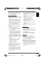
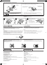
B
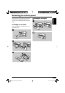
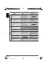
Connecting the parking brake wire / µËÕ“¬‡∫√°¡◊Õ
When installing the monitor in a location where it can be seen by the driver
ËÕ®–µ‘¥µ—È߮աÕ𑇵Õ√Ï„πµ”·ÀπËß∑’˺ŸÈ¢—∫“¡“√∂¡Õ߇ÀÁπ‰¥È◊¡
Connect the parking brake wire to the parking brake system built in the car.
°ËÕπ®–µËÕ®Õ¿“æ ¢Õ„ÀÈ·πË„®«Ë“‰¥Èª‘¥‡§√◊ËÕß·≈È«
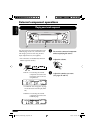
Connecting the crimp connector / «‘∏’µËÕ¢—È«µËÕ”À√—∫Àπ’∫
C
Wire connecting the battery and the parking brake switch.
“¬∑’˵ËÕ°—∫·∫µ‡µÕ√’Ë·≈–«‘µ™Ï‡∫√°¡◊Õ
Contact the metallic part of the crimp to the wires inside.
„ÀÈË«π∑’ˇªÁπ‚≈À–¢Õßµ—«Àπ’∫—¡º—°—∫“¬¢È“ß„π
Pinch the crimp firmly.
Àπ’∫„ÀÈ·πËπ
Parking brake
‡∫√°¡◊Õ
Parking brake wire (light green)
“¬‡∫√°¡◊Õ (’‡¢’¬«ÕàÕπ)
To metallic body or chassis of the car
µËÕ°—∫‚§√ß‚≈À–À√◊Õ‡™´‘¢Õß√∂¬πµ
Parking brake switch
(inside the car)
«‘µ™Ï‡∫√°¡◊Õ (¿“¬„π√∂)
When installing the monitor in a location where it cannot be
seen by the driver
‡
¡◊ËÕ®–µ‘¥µ—È߮աÕ𑇵Õ√Ï„πµ”·ÀπËß∑’˺ŸÈ¢—∫‰¡Ë“¡“√∂¡Õ߇ÀÁπ‰¥È
Connect the parking brake wire to metallic body or chassis of the car.
µËÕ“¬‡∫√°¡◊Õ°—∫µ—«∂—ß∑’ˇªÁπ‚≈À–À√◊Õ‚§√ß√∂¬πµ
Parking brake wire (light green)
“¬‡∫√°¡◊Õ (’‡¢’¬«ÕàÕπ)
°ËÕ•∑”°“•‡™•ËÕ¡µËÕ: µ•«®†Õ•°“•‡¥‘•†“¬‰ø„•••¬•µÏլ˓ߕ–¡—¥•–«—լ˓„ÀȺ‘¥æ•“¥„•°“•‡™•ËÕ¡µËÕ™ÿ¥ª•–°Õ•™ÿ¥•’
°“•‡™•ËÕ¡µËÕº‘¥æ•“¥Õ“®∑”„Àȇ°‘¥§«“¡‡’¬À“¬•È“¬·•ß°—•™ÿ¥ª•–
°Õ••’ȉ¥È“•µ–°—Ë«¢Õ߆“¬‰ø ·•–¢ÕßÕÿª°••ÏµËÕ‡™•ËÕ¡®“°µ—«• ß••Õ“®¡’ ∑’ˉ¡Ë‡À¡•Õ•°—•
1 µËÕ“¬‰ø’µ“¡≈”¥—∫∑’Ë√–∫ÿ„π√Ÿª¥È“π≈Ë“ß
2 ‡™◊ËÕ¡µËÕ°—∫“¬Õ“°“»
3 ÿ¥∑È“¬ µËËÕò«π§«∫§ÿ¡°“√‡¥‘𓬉ø‡¢È“°—∫™ÿ¥ª√–°Õ∫™ÿ¥π’È
Antenna terminal
¢—È«µËÕ“¬Õ“°“»
*
2
Before checking the operation of this unit prior
to installation, this lead must be connected,
otherwise power cannot be turned on.
*
2
°ËÕπ°“√µ√«®Õ∫°“√∑”ß“π¢Õß™ÿ¥ª√–°Õ∫π’È°ËÕπ∑’Ë®–µ‘¥µ—Èß
µÈÕßµËÕ“¬µ–°—Ë«π’È°ËÕπ ¡‘©–π—Èπ®–‰¡Ë“¡“√∂‡ª‘¥‡§√◊ËÕ߉¥È
Attach the parking brake wire to this point
Õ“¬‡∫√°¡◊Õ∑’Ë®ÿ¥π’È
Instal3-4_SV3105_004A.indd 3 3/17/05 11:51:48 AM