


4
English
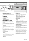
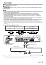
Controls
This is a 4 channel amplifier including 2 stereo amplifiers in a body. One amplifier is referred to
as amplifier A and the other is amplifier B. This unit is compatible with a large variety of
systems by combining the switches and functions described in the following.
L
R
L
R
LINE IN
P.CON EXT.AMP.CONT.
GND
MONO
LINE OUT
25Hz
15Hz
INFRASONIC FILTER OPERATION
OFF
0.2
0.5
5
1
2
3
4
BB AA +
(MAX)(MIN)
25Hz
15Hz
INFRASONIC
FREQ (Hz) FREQ (Hz)
OFF
LPF
OFF
HPF
MONO
STEREO
FILTER
LPF
OFF
HPF
OPERATION
MONO
STEREO
B.M.S.
B.M.S.
FREQ(Hz)
B.M.S.
(
+
6)
CLOSE
OPEN/ B.M.S.
(REMOTE)
INPUT SELECT
A
AB
CONTROL
INPUT SENSITIVITY(V)
0.2
0.5
5
1
2
3
4
10050
80
(MAX)(MIN)
INPUT SENSITIVITY(V)
A
CONTROL
B
LEFT
BRIDGED
RIGHT
SPEAKER OUTPUT
FUSE(20A×4)
BATT.
GND
B
B
A
A
20
20
20
20
$
%
*
@
25Hz
15Hz
INFRASONIC FILTER OPERATION
OFF
0.2
0.5
5
1
2
3
4
(MAX)(MIN)
FREQ (Hz)
LPF
OFF
HPF
MONO
STEREO
INPUT SELECT
A
AB
CONTROL
INPUT SENSITIVITY(V)
A
#
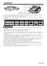
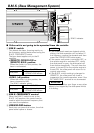
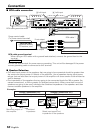
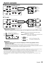
1 42 3
7896 0!
5
1
Fuse (20 A
×
4)
2
Battery terminal
3
Ground terminal
4
Amplifier A speaker output
terminals
5
Amplifier B speaker output
terminals
❖
SPEAKER OUTPUT terminals
• Stereo Connections:
When you wish to use the unit as a stereo
amplifier, stereo connections are used.
The speakers to be connected should
have an impedance of 2Ω or greater.
When multiple speakers are to be
connected, ensure that the combined
impedance is 2Ω or greater for each
channel.
• Bridged Connections:
When you wish to use the unit as a high-
output monaural amplifier, bridged
connections are used. (Make connections
to the LEFT channel (+) and the RIGHT
channel (-) SPEAKER OUTPUT terminals.)
The speakers to be connected should
have an impedance of 4Ω or greater.
When multiple speakers are to be
connected, ensure that the combined
impedance is 4Ω or greater.
The rated input of the speakers should be
no less than the maximum output of the
amplifier. Otherwise malfunction may
result.
6
RCA cable ground lead terminal
7
Amplifier A LINE IN terminal
8
Amplifier B LINE IN terminal
9
LINE OUT terminal
These jacks output respectively the signals
input to amplifiers A and B. They always
output the stereo signals regardless of the
position of the OPERATION switch.
0
Power control terminal
!
EXT.AMP.CONT. (external
amplifier control) terminal
This controls the B.M.S. (See P.6).
2CAUTION
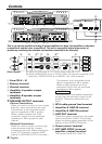
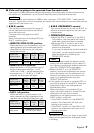
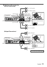
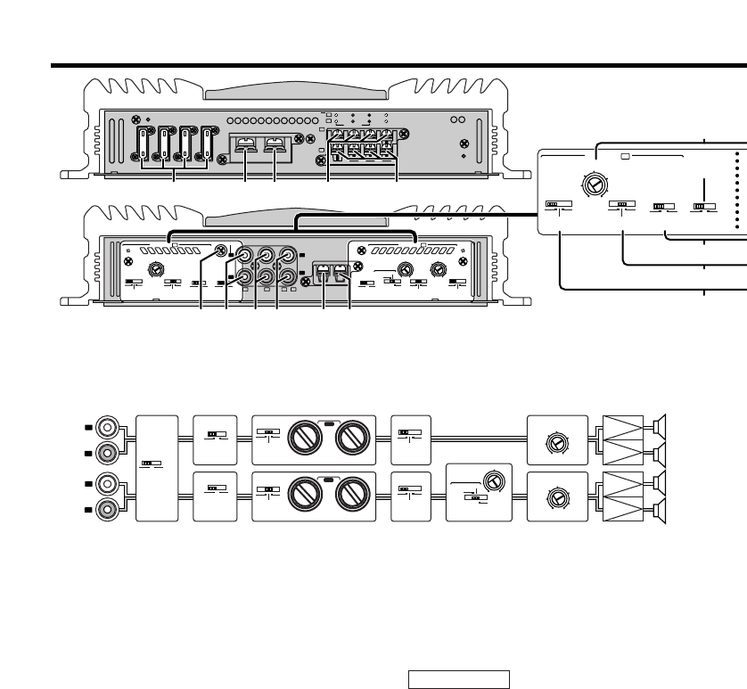
L
R
L
R
A
B
LO PASS
50 50200 200
HI PASS
LO PASS
50 50200 200
HI PASS
A
B
25Hz
15Hz
INFRASONIC
FILTEROPERATION
OFF
25Hz
15Hz
INFRASONIC
FREQ (Hz)
FREQ (Hz)
OFF
LPF
OFF
HPF
MONO
STEREO
FILTER
LPF
OFF
HPF
OPERATION
MONO
STEREO
INPUT SELECT
A
AB
0.2
0.5
5
1
2
3
4
(MAX)(MIN)
INPUT SENSITIVITY(V)
0.2
0.5
5
1
2
3
4
(MAX)(MIN)
INPUT SENSITIVITY(V)
@#$%&^ *
#1 #2
B.M.S.
B.M.S.
FREQ(Hz)
B.M.S.
(
+
6)
CLOSE
OPEN/ B.M.S.
(REMOTE)
10050
80
#1 When FILTER is set to LPF, the sound is monaural (L+R).
#2 When INFRASONIC is set to 15Hz or 25Hz, the sound is monaural (L+R).
* Note that if OPERATION is set to MONO, Lch is still monaural.
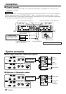
Block diagram