


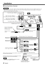
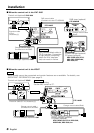

TO MZ-BUS
BATT
ACC
BATT
ACC
ILLUMI
P.CONT
TEL MUTE
FM•AM TUNER 44W×4 AMPLIFIER
HIDEAWAY UNIT
KTC-1000R
ANTENNA INPUT POWERPREOUT
REAR/NON-FAD FRONT
SUB WOOFER
REAR SPEAKER
FRONT SPEAKER
DAB
CHANGER
SLAVE UNIT
TV MONITOR
FM ANTENNA
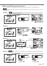
TO 5L I/F
BATT
ACC
PREOUT
REAR/NON-FAD FRONT
1
2
3
4
5
6
7
8
1
2
3
4
5
6
7
8
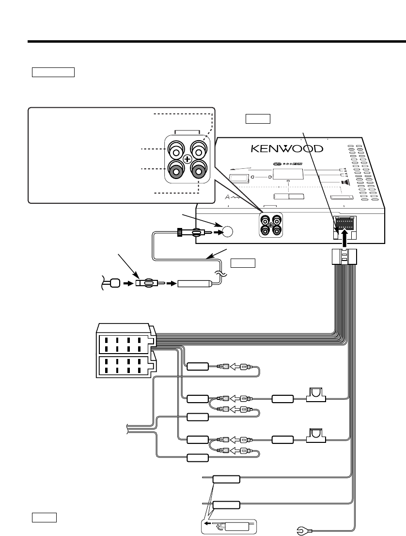
Installation
4
English
Wiring harness (5.5m) (Accessory5)
Rear left output (White) /
Non-fading left output (White)
Rear right output (Red) /
Non-fading right output (Red)
Front left output (White)
Front right output (Red)
FM/AM antenna input
Battery cable (Yellow)+12V
Ignition cable (Red)+12V
Automatic illumination control cable (Orange)
Ground cable (Black) -
(To car chassis)
Connect to the terminal that is grounded when either
the telephone rings or during conversation.
Power control cable (Blue/ White)
TEL mute cable (Brown)
To connect the KENWOOD navigation system,
consult your navigation manual.
NOTE
If you connect the ignition cable (red) and the battery cable (yellow) to the car chassis (ground), you
may cause a short circuit, that in turn may start a fire. Always connect those cables to the power
source running through the fuse box.
2WARNING
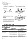
Antenna Cord (Accessory6)
Route wiring away from power
circuitry to avoid noise.
NOTE
Antenna Cord
(ISO)
Antenna Conversion
Adaptor (ISO–JASO)
(Accessory8)
When using the optional power amplifier, connect to
its power control terminal.
Fuse
(10A)
Fuse
(3A)
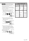
Connecting Cables to Terminals
■
(5.5m)
Do not put anything into the fuse holder.
NOTE
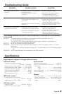
Connector B
Connector A
Connect to control unit
power supply terminal.
If no connections are
made, do not let the cable
come out from the tab.