


12
1
2
3
4
5
6
7
8
9
10
11
12
13
14
15
16
17
18
19
20
21
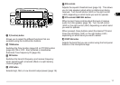
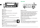
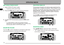
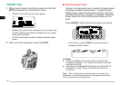
REAR PANEL
qq
qq
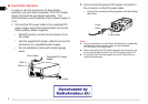
q Antenna connector
Connect an external antenna {page 5}. When making test
transmissions, connect a dummy load in place of the
antenna. The antenna system or load should have an
impedance of 50 Ω. The TM-V7E accepts a male N-type
connector and other versions accept a male PL-259
connector. This transceiver has only one antenna
connector because of a built-in duplexer.
ww
ww
w Power Input 13.8 V DC cable
Connect to a 13.8 V DC power source. Use the supplied
DC power cable {pages 3 and 4}.
ee
ee
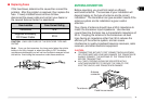
e Speaker jacks
If you wish, connect an optional external speaker for clearer
audio. These jacks accept a 3.5 mm (1/8") diameter,
2-conductor plug. See page 6 for more information.
!3!3
!3!3
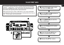
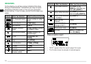
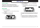
!3 MNU button
Selects the Menu mode {page 19}.
!4!4
!4!4
!4 PM button
Selects the Programmable Memory mode {page 36}.
!5!5
!5!5
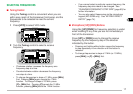
!5 PWR switch
Switches the transceiver ON or OFF {page 16}.
!!
!!
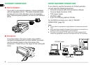
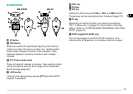
!6 Microphone connector
Insert the 8-pin modular connector plug until the locking tab
"clicks".
!7!7
!7!7
!7 DATA connector
Connect a Terminal Node Controller (TNC) for Packet
operation. Accepts a 6-pin mini DIN plug {page 6}.
PWRPWR
CALLCALL
UP
DC 8 V, 200 mA max.
GND
STBY (PTT)
GND (MIC)
MIC
NC: No connection
DWN