


2
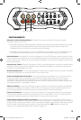
CX.5-SERIES AMPLIFIERS
OWNER’S MANUAL
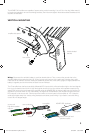
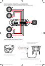
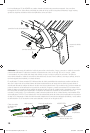
INSTALLATION
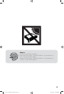
Mounting: Choose a structurally sound location to mount your KICKER amplifi er. Make sure there are no items
behind the area where the screws will be driven. Choose a location that allows at least 4” (10cm) of open
ventilation for the amplifi er. If possible, mount the amplifi er in the climate-controlled passenger compartment. Drill
four holes using a 7/64” (3mm) bit and use the supplied #8 screws to mount the amplifi er.
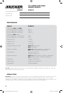
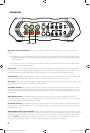
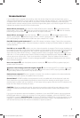
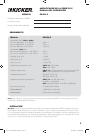
PERFORMANCE
Authorized KICKER Dealer:
Purchase Date:
Serial Number:
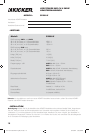
Model: CX600.5
RMS Power, AMP1 and AMP2
@ 14.4V, 4 stereo, 1% THD+N
@ 14.4V, 2 stereo, 1% THD+N
@ 14.4V, 4 mono, 1% THD+N
40W x 4
75W x 4
150W x 2
RMS Power, SUB channel
@ 14.4V, 2 mono, 1.5 % THD+N
@ 14.4V, 4 mono, 1.5 % THD+N
300 x 1
150 x 1
Length | in [mm] 14 [360]
Height | in [mm] 2-3/8 [60]
Width | in [mm] 7-3/16 [180]
Frequency Response ± 1dB AMPS 1-2: 10Hz–20kHz
SUB: 25Hz–200Hz
Signal-to-noise Ratio AMPS 1-2: >95dB, A-weighted, re: rated power
SUB: >90dB, A-weighted, re: rated power
Input Sensitivity Low Level: 125mV–5V
High Level: 250mV–10V
Electronic Crossover AMPS 1-2: HI/OFF [bypass], 50–200Hz, 12dB/octave;
SUB: Variable low-pass, 50–200Hz, 24dB/octave
Bass Boost Variable 0–12dB @ 40Hz
Subsonic Filter 24dB/Octave, Fixed @ 25Hz
Remote Bass: Yes [sold separately]
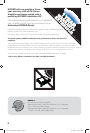
Pro Tip: To get the best performance from your new KICKER Amplifi er and extend the warranty by 1 year, use
genuine KICKER accessories and wiring.
MODEL: CX600.5
2012 CX 5-Channel Amp Rev F.indd 22012 CX 5-Channel Amp Rev F.indd 2 6/22/2012 3:08:47 PM6/22/2012 3:08:47 PM