


7
SX .1 Series Amplifiers
Installation
Mounting
When selecting a location to mount your Kicker amplifier be
sure it is structurally sound and that there are no items
behind the area that could be damaged by the screws. Check
for wiring, brake lines, fuel lines, gas tanks, etc.
All amplifiers generate heat under normal operation. Be sure
to choose a location that allows adequate ventilation for the
amplifier. Also consider that the air temperature inside an
automobile’s trunk can reach upwards of 140 degrees fahren-
heit. An amplifier mounted in the trunk may require additional
cooling such as extra fans moving air around the amplifier’s
chassis or ventilating the trunk to exchange the hot air in the
trunk for cooler air outside. If possible, mounting the amp in
the passenger compartment will allow cooler operation.
Remember that the controls on top of the amp will need to
be accessible for adjustment later. Keep this in mind as you
choose your amplifier’s mounting location.
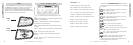
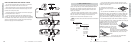
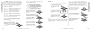
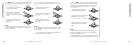
Now that you are ready to mount your amplifier, use the
supplied 3mm allen wrench to remove the amplifier EndKaps.
This will give you access to the mounting holes in the amplifi-
er and all wiring connections.
See Fig. 1
Remove Remov
e
Remove
Remov
e
M1 M2 M3 M4
ESC ENT
HOME
R
SYS
MEM-1
GAINEQLPFHPF KOMP
AMP1
LOCK
MEM-2 MEM-3 MEM-4
PHASE
MUTE
AMP2
LEFT RIGHT
** kicker
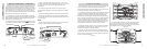
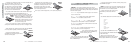
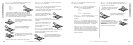
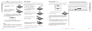
With the EndKaps removed, you now have access to the
four mounting holes in the mounting feet and all wiring
connections. Drill 4 holes using a 7/64” drill bit and use the
supplied #8 screws to mount the amplifier.
See Fig. 2
R
M1 M2 M3 M4
ESC ENT
HOME
SYS
MEM-1
GAINEQLPFHPF KOMP
AMP1
LOCK
MEM-2 MEM-3 MEM-4
PHASE
MUTE
AMP2
LEFT RIGHT
** kicker
Fig. 1
Fig. 2
6
SX .1 Series Amplifiers
Features
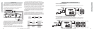
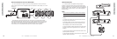
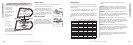
End Panel Views
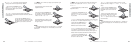
The BLAST Port is used to connect the Remote Bass Level
Controller and for transferring control signals from one SX
amplifier to another SX amplifier. An RJ45 cable is required to
connect the BLAST Port (Out) of one amp to the BLAST Port
(In) of another. This is only required if you want to control
more than one amplifier with the same Bass Level Controller.
More details on this further in the manual.
The speaker terminals are custom-machined connectors
with full protective shrouds and are designed to accept heavy
gauge speaker wire assures maximum power transfer and
damping with minimal power loss.
Gold-plated RCA input connectors and
PAST
jacks provide
solid input and output connections for your pre-amp signal.
Speaker +
Speaker -
Left Input
Left PAST
Right Input
Right PAS
T
BLAST Port In BLAST Port Out
XX
XX
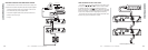
Ground
Remote
+ 12 Volt
Fusing
Power LED
Check Fuse LED
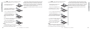
Custom-machined power block accepts up to a 2 Ga wire
for both power and ground connections and up to an 8 Ga for
remote turn-on assures maximum power transfer with
minimal loss.
On-board fusing (number of fuses vary by amp size) to
protect amplifier against over current conditions and reverse
polarity.
Power LED indicates amplifier is powered up and operating.
Check Fuse LED indicates a fault with the end panel fuses.
This could be fuses which are not seated properly, faulty fuses
or blown fuses.
NOTE...
SX1250.1 does not have on-board fusing or the Check Fuse
LED due to larger external fusing requirements.