


9
SX .1 Series Amplifiers
Installation
System Diagrams
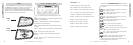
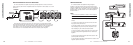
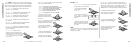
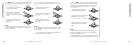
SINGLE SPEAKER OR VOICE COIL
SX.1 series amplifiers are capable of operating into a minimum impedance of 2 ohms
(SX650.1) or 1 ohm (SX1250.1).
+
_
GROUND
REMOTE
TURN-ON
BATTERY
+12V
FUSE
18"
or less
S+
S-
ESC
HOME
ENT
M1
AMP 1
LOCKLEFTSYS RIGHT MUTE
AMP 2
GAINEQ LPF HPF PHASEKOMP
8888888888.........
M2 M3
M4
SIGNAL OUT
SIGNAL IN
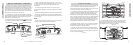
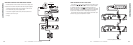
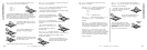
MULTIPLE SPEAKERS OR VOICE COILS PARALLEL WIRED
SX.1 series amplifiers are capable of powering multiple speakers or voice coils wired in
parallel as long as the minimum impedance does not drop below 2 ohms (SX650.1) or 1
ohm (SX1250.1).
GROUND
REMOTE
TURN-ON
BATTERY
+12V
FUSE
18"
or less
S+
S-
ESC
HOME
ENT
M1
AMP 1
LOCKLEFTSYS RIGHT MUTE
AMP 2
GAINEQ LPF HPF PHASEKOMP
8888888888.........
M2 M3
M4
SIGNAL OUT
SIGNAL IN
+
_
+
_
+
_
+
_
8
SX .1 Series Amplifiers
Installation
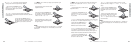
Wiring
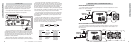
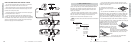
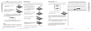
Signal is input into the amplifier using the low level RCA
input connections. If your source unit does not have RCA
output connectors you will need to use a Hi-Lo level signal
adapter. See your Kicker dealer for more details on this.
The output (PAST) RCA jacks provide an unaltered signal
output to feed another amplifier or component.
SOURCE UNIT
The use of twisted pair interconnects is recommended for
all installations to minimize noise. When routing these cables
through the automobile, try to keep them away from factory
wiring harnesses and other power wiring. If you need to cross
any of this wiring do so at a 90 degree angle to reduce the
possibility for noise problems.
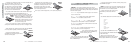
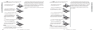
When working with power connections it is always recom-
mended that you disconnect the battery to prevent accidents.
The ground should be connected to the amplifier first
before making any of the other connections. This wire should
be as short as possible (24 inches or less) and connected to a
paint/corrosion free solid metal area of the car’s chassis. Use
the same gauge wire as recommended for the amplifier’s
power connection to the battery. Adding an additional ground
wire between the car battery’s negative post and the car chas-
sis of this same gauge (or larger) is also recommended.
If you ever need to remove the amp from the vehicle after
it has been installed, the ground wire should be the last wire
disconnected from the amplifier, just the opposite of when
you installed it.
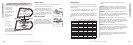
A fuse must be installed within 18 inches of the battery to
protect the power wire feeding your amplifier. This fuse
should be of at least the same value used in the amplifier but
no higher than the capacity of the power wire. See the charts
below for wire size and fusing recommendations.
Model Fuse Size Wire Size
Wire Size Length Maximum Fuse
SX650.1
SX1250.1
60A
150A
4 GA
2 GA
8 Ga
4Ga
2 Ga
0Ga
8 Ga
4 Ga
2 Ga
0 Ga
Less than
10 feet in
length
70 Amps
175 Amps
250 Amps
400 Amps
40 Amps
90 Amps
150 Amps
200 Amps
10 feet to
20 feet in
length