


8
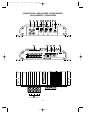
CONTROLS AND INDICATORS
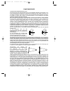
10 • SUB OUTPUT PHASE ADJUSTMENT: It allows the continuous phase adjustment in the
region comprised between Min and Max of the SUB output compared to the
FRONT and REAR outputs. The easiest way to determine the “Wave
Alignment” is to use a third-of-octave sound analyzer. Utilize a CD with a
pink noise track and position the microphone exactly at ear level in the
driver’s seat. Adjust the Wave Alignment as follows:
Turn the potentiometer of the “Wave alignment” until the crossover point
between the SUB section and the other sections reaches the maximum
value. The audio analyzer will display the maximum increase.
If the same adjustment is to be made without the relevant instrument, one must rely on his
own ears. Utilize again a CD with a pink noise track or a well known sound track.
Turn the Wave Alignment potentiometer until low frequencies increase.
11 • SPEAKER CONNECTOR: Outputs for speaker connection. The amplifier allows to
connect speakers with minimum 2-ohm impedance per channel.
NOTE: No mono or mixed-mono bridge configuration is possible.
Be sure to keep the right polarity and phase in connecting the speakers.
Avoid any contact between poorly insulated wires and the car’s ground or metal pieces and
between the wires themselves.
12 • BAT + CONNECTOR: to be connected directly to battery + by means of a fuse located
close to the battery itself. Utilize a cable having an adequate section. Do not connect this
cable to the car’s electrical system wiring (eg.: dome-light circuit, car radio etc.)
13 • GND CONNECTOR: connect the ground terminal to a clean base metal part of the
vehicle chassis (if possibile, to an existing screw). Utilize a cable having an adequate section.
14 • REMOTE-ON CONNECTOR: to be connected either to the remote switch-on output lead
or to the output lead of the power antenna coming from the head unit. As a resul, the 45.40
will be switched on and off simultaneously with the head unit.
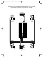
15 • CHECK CONTROL LED: this led shows the amplifier’s status of operation :
WHITE: the unit is off
GREEN: the unit is working OK
RED: the unit has entered the protection mode
The 45.40 is equipped with three different protection devices:
Overheating: in case of wrong installation the unit enters the protection mode before being
damaged. As soon as the temperature returns to normal values, the unit resumes normal
operation.
Overload: if several speakers are connected to the amplifier and the total impedance
decreases below the allowable threshold (0.5 - 1 ohm), the amplifier enters automatically the
protection mode to avoid any damage. To restore normal operation the head unit has to be
switched off and then on again.
Output short circuit: in case of a short circuit at the speakers outputs, the unit enters the
protection mode to avoid serious damage to the end stage transistors. Normal operation is
restored by eliminating the short circuit and by switching on the head unit again.
Min. Max.
O/M 45.40 (5T) 25/06/02 19:25 Page 8