


23
Maintenance / Color Calibration Procedure
■ Screen Cleaning
Periodically clean the screen surface using ammonia-free cleaning wipes (Marshall Part No. V-HWP-K).
A clean micro-ber cloth can also be used using only non-abrasive and ammonia-free cleaning agents.
Do not use paper towels. Paper towel bers are coarse and may scratch the surface of the polycarbonate
faceplate or leave streaks on the surface. Antistatic and ngerprint resistant cleaning agents are recommended.
Do not apply excessive pressure to the screen to avoid damaging the LCD.
■ Faceplate Dusting
Dust the unit with a soft, damp cloth or chamois. Dry or abrasive cloths may cause electrostatic charge on the
surface, attracting dust particles. Neutralize static electricity effects by using the recommended cleaning and
polishing practice.
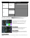
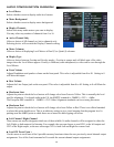
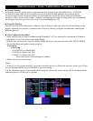
■ Color Calibration Procedure
• Allow both the unit you want to calibrate and the Minolta® CA-210 to warm up for a minimum of 20 minutes.
• Attach the CA-210 color probe to the update dongle.
• With the unit still turned on, insert the update dongle into the service port at the rear of the OR-841-HDSDI.
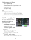
• Use the RotoMenu navigation control and go to:
Color Menu
Color Temp
• Cal D65/D93 to calibrate both
• Cal D65 to calibrate only D65
• Cal D93 to calibrate only D93
Press enter once to select and again to conrm
• Follow the on-screen instructions
Notes:
1. If there is no color probe attached or you make a mistake and try to calibrate the incorrect screen, you will get
an error message and the screen will default to previous settings.
2. If the calibration process is interrupted while in progress, the current screen settings will be corrupted and the
calibration process will have to be repeated.
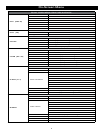
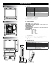
■ VIDEO INPUT/OUTPUT
HD/SD-SDI Video Input / Output
■ CONNECTORS
Video Input - 2 x BNC Female (75 Ω)
Video Output (Active Loop-Through) - 1 x BNC Female (75 Ω)
Parallel Remote - RJ-45
Optional Input Slot
Audio Output Jacks - 3.5mm Stereo x 2. One Front and One Rear.
Service Terminal
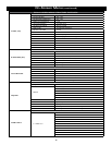
Power Input - 4-Pin Male XLR
Pin 1: GND
Pin 2: N/C
Pin 3: N/C
Pin 4: +12VDC
■ ELECTRICAL
Power Consumption - 1.5 Amp (Max) @ 12VDC (18W Max)
Voltage Requirement - 12VDC (10VDC-18VDC)
■ MECHANICAL