


• Native display for 1080i images
• TFT-MegaPixel™ totally digital end to end signal processing
• 16ms pixel response measured worst case black to white to black
• 180 degree viewing angle in all directions
• Multiple format acceptance for virtually any analog or digital video signal
• Display PC Signals to XGA 1024x768
• Frame Marker Screen Overlay with curser and safe area
• ColorMatch Conversion™ with SMPTE/EBU color space emulation of CRT
• 98% SMPTE/EBU Color Gamut
• Color temperature presets for D75, D65, D55, and user adjustable
• HyperProcess™ motion interpolation of interlace images
• On screen display of input status, formats, and menu functions
• Pixel to Pixel™ native resolution display
• Lightweight – 75% lighter than CRT models
• Settings memory restores active state with power off/on cycle
• Direct front panel selection of all functions
• Blue Gun for adjustment to SMPTE color bars
• Includes V-PS24-7.5 Universal power supply (U.L. class 2)
• Three LEDs (Red, Green, Amber) produce 7 different tally indications
1
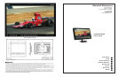
Product Overview
The V-R231P-AFHD features our Completely Digital TFT-Megapixel™ system and can display native high defi nition images on
the LCD/TFT screen with 6.9 million pixels. Analog signals are digitized using an advanced 10 bit process with 4x over sampling
and adaptive 5 line comb fi lter plus exacting color space conversion. Video is scaled to fi t on screen in the highest resolution
using a state of the art LSI that incorporates adaptive 7x7 pixel interpolation and precision Gamma correction to product the best
images available. Additional features include, Pixel-to-Pixel™ native resolution scaling, setup memory, 6 Frame Marker Overlays,
Blue Gun, and direct access for all adjustment and selection functions The V-R231P-AFHD has been designed for fi eld and studio
applications with a rugged, all metal enclosure and optional optical grade screen protection. A VESA 75mm mount is included and
can be used with optional desktop or rack mounted systems.
2
Features
3
Electrical Specifications
Screen Aspect 15:9/16:9/4:3 switchable
Display (Viewing Area) 23 Inch diagonal (495.36mm w x 309.6mm h)
Viewing Angles
180 ̊ in all directions
Resolution (RGB Dots) 1920H×RGBx1200V (6.9 million pixels)
Color Depth 16.7 Million Colors (8-Bit)
Dot Pitch .258mm square pixel
Contrast Ratio 500:1
Pixel Response 8.5ms rise/7.5ms fall (measured black to white to black)
Brightness (in cd/m²) 250 cd/m²
Backlight Field Replaceable CCFL (50,000 hour half life)
LCD Screen Treatments Anti Reflection, Anti Glare, Hardcoat plus 3mm thick protective cover
Estimated MTBF 5 years of 24/7/365 operation
System NTSC/PAL with auto recognition
Inputs per display HDSDI/SDI (SMPTE259M, 292M) (ITU-R-BT601) per screen (BNC)
YPrPb Component (3 BNC)
Composite Video PAL/NTSC auto detect (BNC)
S-Video (Y/C) (4 Pin Mini Din female)
XGA 15Pin HD-15 Female
DVI 27 (Pin DVI-I Female)
Tally (HD-15 Female)
Active Outputs HDSDI/SDI (SMPTE259M, 292M) (ITR-U601) per screen (BNC)
YPrPb Component (3 BNC)
Composite Video PAL/NTSC auto detect
S-Video (Y/C) (4 Pin Mini Din female)
Color temperature
D55, D65, D75, 6300 ̊ K
Color Gamut SMPTE-C/EBU 98% CIE
Luma Linearity Typical +/- 3% with 5 ire increments (0 to 10 ire)
Power Required 24 VDC
Power Consumption Approx. 70 watt nominal
Operating temperature
32 ̊ F to 120 ̊ F (0 ̊ C to 50 ̊ C)
Storage temperature
-4 ̊ F to 120 ̊ F (-20 ̊ C to 50 ̊ C)
Compliance
₠, FCC-Class A, ANSI-63.4 (Certificates on file)
RoHS WEE / Environmental
Do not dispose. Return to Manufacturer or Authorized Recycle Facility
5
2
V-R231P-AFHD
V-R231P-AFHD
Users Guide
Users Guide
Marshall Electronics
Video Screen Formats and Frame Rates
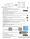
9. Overlay Enable
Must be turned on to enable Frame Marker, Center Mark and Safe Area functions.
10. Frame Marker (Only active in 16:9 display mode) (Requires OVL to be enabled)
Frame Aspect Markers appear as RED lines that are used to frame the image for an additional screen format when 16:9 display
is enabled. For example 4:3 marker is often used for HD broadcasts that are also down converted and cropped for SD trans-
mission. Frame markers are available for 4:3, 15:9, 14:9, 13:9, 1.85:1, 2.35:1 and 2.37:1 screen aspects.
11. Center Mark (Requires OVL to be enabled)
A cross hair cursor is placed on the middle of the screen. The lines of the cross hair consist of a center white element that is
4 pixels wide, surrounded by a black border on each side that is 2 pixels wide. Use of black and white for the Center Mark
function allows the viewer to see screen center in all ranges of color for the screen image.
12. Safe Area Overlay (Requires OVL to be enabled)
A shaded border is placed onto the edge of image indicating a user selected area deemed to be safe for graphic and
other image placement. Safe Area overlays are available that indicate 80%, 88%, 90%, and 93% of the displayed im-
age. The safe area displays for the selected screen aspect.
13. Image Adjustment Controls
Use to adjust image appearance on the screen. The tint control will only function for NTSC composite and
S-Video sources and is not available in all other formats. Each knob has a center detent position that approxi-
mates a normal setting calibrated to standard SMPTE color bars.
14. HyperProcess™ Interlace Image Motion Compensation (Disabled for progressive and PC formats)
Holding OSD then tapping TEMP will toggle through 3 selections of interlace motion compensation.
Interlace images such as 1080i and 480i must be converted to progressive images for presentation on the LCD/TFT screen. This is
accomplished via 3 user selected interpolation programs. Default, MC-1 and MC-2.
Interpolations are performed based on motion of individual pixels in 7x7 pixel groupings for luminance and chrominance. Motion is
detected in horizontal, vertical, and diagonal directions.
The default setting uses inter-fi eld interpolation processing to create an image based on fi eld 1 plus fi eld 2 changes and outputs to
the screen 60 or 50 times per second based on input frame rate. Each frame is made up of the current fi eld information plus changes
detected in the transition from the previous fi eld. There is a one frame propagation delay in this mode.
MC-1 – Intra-fi eld interpolation processing is used to transform each fi eld into a single progressive frame based upon information
within the fi eld. There is a single fi eld propagation delay in this mode.
MC-2 – Uses inter-fi eld processing to generate true frame of fi eld one plus fi eld 2 with no motion compensation. Images are presented
via a segmented frame system that creates progressive frames based upon 2 half image samples of odd and even lines much the
same as CRT processing for interlaced images. Motion artifacts will appear as jagged edges in this mode since fi eld one and fi eld
two frames are displayed simultaneously with no compensation for spatial motion during the sample period. MC-2 has a one frame
propagation delay.
V-R231P-AFHD Optional Accessories
Stand
VP-LCD171H-ST01
Use for table top mount
Rack Mount Kit
VPRACKARM
Attaches monitor to standard 19” Rack
Dimensions 20.88” w x 15.03” h x 3.0” d (53.28cm x 38.18cm x 7.5cm)
V-R231P-AFHD Weight 16.3 lbs (7.38 kg)
V-PS24-7.5 Power Supply Weight 1.6 lbs (0.7kg)
4
Mechanical Specifications
All signal types and frame rates are automatically detected
• 525 –60i / 625 - 50i (Interlaced NTSC/PAL)
• 720 x 486P (Progressive)
• 720 x 576P (Progressive)
• 1280 x 720– Analog-50P, 59.94P, 60P /Digital 23.97P, 24P, 25P, 50P, 59.94P, 60P (Progressive)
• 1035 x 1920 - 59.94i, 60i (Interlaced)
• 1080 x 1920 – 50i, 59.94i, 60i / 23.973Psf, 24Psf, 25Psf, 29.97Psf, 30Psf
Psf=Progressive
or Segmented
Frame formats
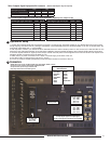
8. Blue Gun & Mono (Monochrome Black & White)
Use to adjust SMPTE or split fi eld color bars.
1. Allow monitor to warm up for 15-20 minutes minimum. Adjustments will not be accurate on a cold monitor.
2. Display SMPTE color bars on monitor. Turn on Mono
3. Find the PLUGE (superblack, black, and gray bars) at the lower right of the pattern. Adjust BRIGHT-
NESS control until there is no difference visible between the superblack and black bars, but a difference is
visible between the black and gray bars.
4. Adjust CONTRAST control to achieve a balanced gray scale across top bars.
5.Turn off Mono then turn on BLUE GUN
6. Turn up CHROMA (color level) control until the two outermost bars (white and blue appear to match in brightness.
7. NTSC Only -Adjust COLOR PHASE (tint or hue) control until the third bar from the left (cyan) and
the third bar from the right (magenta) appear to match in brightness.