


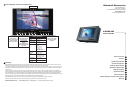

V-R65P-HD Users Guide
Marshall Electronics
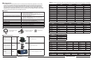
Optional Accessories (continued)
Replacement
Protection Screen
V-R65-RPS
Use to replace damaged or scratched protective
cover for screen
Rack-mount kit A V-R65-1M (Image not available) Single monitor mount for 19” rack
Rack-mount kit B V-R65-2M (Image not available) Dual monitor mount for 19” rack
Component input cable RGB-5HD15-X HD-15 to BNC break out cable
(X = Length in feet 6, 10, 15, 20)
Power Adapter Cable V-PAC-D
Use with Anton Bauer D-type connection
Power Adapter Cable V-PAC-XLR Use with 4 Pin XLR connections
Mount for IDX Batteries V-R65-BA Attaches to V-R65P-HD monitor
Sequential 2 channel
charger
IDX-VL-2Plus
2-channel sequential charger with a built-in 60W power sup-
ply. Charges 2 ENDURA E series batteries in fewer than 5
hours. One 10’ XLR cable included.only 2 lbs
Sequential 4 channel
charger
IDX-VL-4
Economically charges 4 ENDURA E series batteries in under
6 hours using Full Power Charge (FPC) method
Simultaneous 4 channel
charger
IDX-VL-4S Charges 4 ENDURA E series batteries in 2.5 hours or less
55 W Lithium Battery IDX-E50S
V-Mount battery pack with 3 LED power Indicator
55 W Lithium Battery
with Power Link IDX-E50
V-Mount Battery Pack with PowerLink includes accurate
Power Status Display and supports Digi-View
82 W Lithium Battery IDX-E80S
V-Mount battery pack with 3 LED power Indicator
82 W Lithium Battery
with Power Link
IDX-E80
V-Mount Battery Pack with PowerLink includes accurate
Power Status Display and supports Digi-View
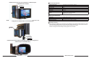
1. Unpack the V-R65P-HD and accompanying V-PS12-5V-1 power supply. Physically inspect for any damage that may
have occurred during shipping. Should there be any damage, immediately contact Marshall Electronics at 800-800-
6608. If you are not located within the continental united states call +1 310-333-0606.
2. Connect required cables for signal input and output.
Please note that power must be applied to the V-R65P-HD for the HDSDI/SDI and composite outputs to be
activated. All BNC connectors should be rated for 75
Ω.
3. Plug the V-PS12-5V-1 power supply into the A.C. source
Please note that power can be supplied from a variety of DC sources, such as batteries or Vehicle power.
Input power range is 10.7 to 15 Volt D.C. In operation, the V-R65P-HD will draw approx. 0.8 amp.
Attach twist lock power connection from V-PS12-5V-1 power supply to the back of the unit.
4. Turn on the V-R65P-HD by depressing the power switch located on the front of the unit.
8
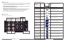
Operational Setup
* Tally lamps active when connected to ground
HDSDI or SDI in.
270Mbs to 1.5Gbs
Automatically
terminates to 75Ω
Refer to Table 3
for signal types
Composite Video IN
NTSC/PAL
Automatically
terminates
to 75Ω
Component Video
or VGA INPUT
HD-15 Female refer
to Table 1 for signal
pin outs and Table 2
for Signal Types
Re-Clocked
HDSDI/SDI Output.
Signal in equals
signal out
Active
Composite
Output
Pin1- Green
Pin2- Red
Pin3-Amber
Pin4 Gnd -
Pin5-
Pin6-
Pin7-
Pin8-
Pin 9-
Pin10-
Pin11-
Pin12-
Pin13-
Pin14-
Pin15-
Tally IN DB-15 Female
10.7 to 15 VDC
V-PS12-5V-1 power supply is
included
Left Pin - Pos. Right Pin- Neg
Input Connectors
9