


14
On-Screen Menu (continued)
VIDEO CONFIGURATION SUBMENU (continued)
■
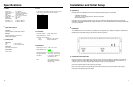
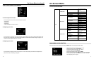
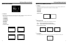
Aspect Ratio Settings
Use to switch between 4:3 and 16:9 aspect ratios.
As the V-R842DP-DVI monitor has a native resolution of 1024 x 768 RGB pixels, incoming images are automatically
scaled to fit the screen:
• In 4:3 mode, images are scaled up or down to fill the entire 4:3 screen (1024 x 768).
• In 16:9 mode, images are scaled to fill the maximum 16:9 portion of the screen (1024 x 576), with black bars filling
the remainder of the screen.
Note: The aspect ratio setting is ignored when Pixel-to-Pixel mode is enabled.
■
Scanning Modes
Use this setting to switch between normal and underscan modes:
• In normal scan mode, the active portion of the video signal is displayed on the screen, with 0% overscan.
• In underscan mode, area around the active video area is displayed on the screen, resulting in blanking intervals
being shown around the perimeter of the active image. Use this mode to clearly view the edges of the active video
area.
■
Delay Modes
Use this setting to enable one of three delay modes (H/V, H, V):
• In H/V delay mode, both horizontal sync and vertical sync are delayed, resulting in both horizontal and vertical
blanking periods being shown on the screen.
• In V delay mode, vertical sync is delayed so that the vertical blanking period is displayed on screen.
• In H delay mode, horizontal sync is delayed so that the horizontal blanking period is displayed on the screen.
Note: Delay modes are only available in normal scan mode.
4:3 Mode
16:9 Mode
7
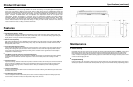
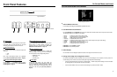
Rear Panel Features
Power Input
Connect the 12VDC input to the 2-Pin twist lock power
input connector. Power can be supplied from the
included power supply, or from a variety of DC sources
supplying at least 3.5 Amps at 12 Volts.
IMPORTANT: If using a power source other than the
included power supply, be sure that the polarity of the
DC input is correct:
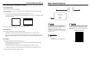
Signal Input/Output
Connections:
• VGA (HD-15)
• DVI (29-Pin connector, DVI-D signals only)
Tally Interface
Each tally light is activated via the HD-15 connector by
connecting the corresponding pin to ground. A variety of
external devices can be used to perform the contact
closure. No additional power should be supplied to the
HD-15 port.
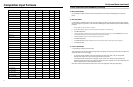
Tally Interface: HD-15 Pinout
Pin No. Signal
1 M1 Green
2 M1 Red
3 M1 Yellow
4 Ground
5 Ground
6 N/C
7 N/C
8 N/C
9 N/C
10 N/C
11 M2 Green
12 M2 Red
13 M2 Yellow
14 Ground
15 Ground
1
2
3
1
2
3