CHAPTER 3: AMPLIFICATION AND AUDIO
14
Loop Output Connector
The male XLR Loop output connector allows multiple
Acheron Designers to be looped from a single audio source.
For applications that require multiple Acheron Designers,
connect the Loop output of the first unit to the Input of the
second, and so forth.
NOTE: The order in which loudspeakers are
connected when looping audio signals is unim-
portant. The Loop connector is wired in parallel to the
Input connector and transmits the unbuffered source
signal even when the Acheron Designer is powered
off.
To avoid distortion when looping multiple Acheron Designers,
make sure the source device can drive the total load imped-
ance of the looped loudspeakers. In addition, the source
device must be capable of delivering approximately 20 dBV
(10 V rms into 600 ohms) to yield the maximum peak SPL
over the entire operating bandwidth of the loudspeakers.
Most professional audio equipment can transmit these
source levels.
To calculate the load impedance for the looped loudspeak-
ers, divide 10 kOhms (the input impedance for a single
Acheron Designer) by the number of looped loudspeakers.
For example, the load impedance for 10 Acheron Designer
loudspeakers is 1000 ohms (10 kOhms / 10). To drive this
number of looped loudspeakers, the source device should
have an output impedance of 100 ohms or less. This same
rule applies when looping Acheron Designer loudspeakers
with other self-powered Meyer Sound loudspeakers and
subwoofers.
NOTE: Most source devices are capable of
driving loads no smaller than 10 times their
output impedance.
CAUTION: Make sure that all cabling for
looped loudspeakers is wired correctly (Pin 1
to Pin 1, Pin 2 to Pin 2, and so forth) to prevent the
polarity from being reversed. If one or more loud-
speakers in a system have reversed polarity, fre-
quency response and coverage will be significantly
degraded.
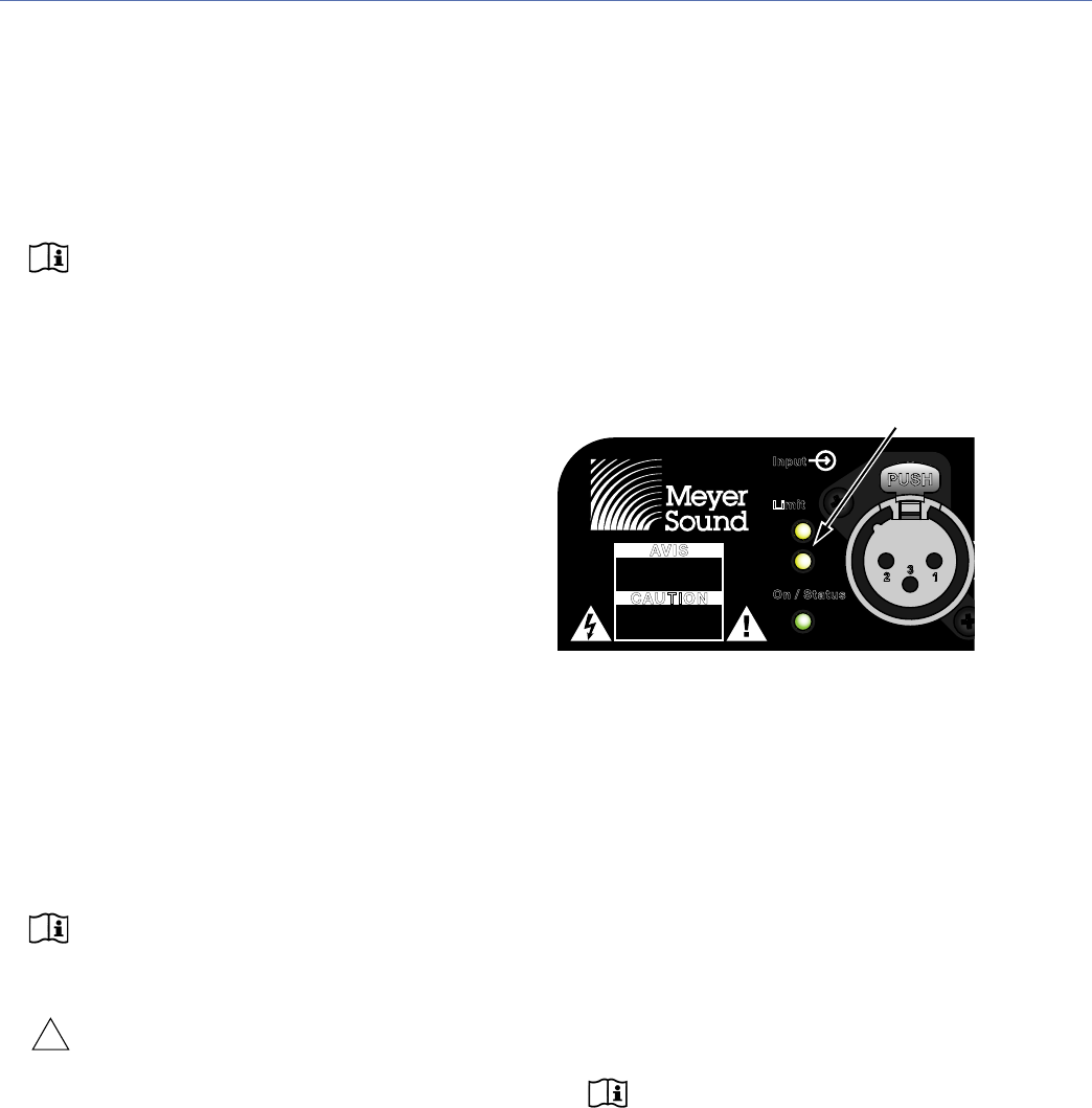
LIMITING
When source levels for the Acheron Designer exceed opti-
mum input levels for its drivers, limiting is engaged and is
indicated by the two Limit LEDs on the rear panel. The bot-
tom LED indicates limiting for the low-frequency channel.
The top LED indicates limiting for the high-frequency chan-
nel. When engaged, limiting not only protects the drivers,
but also prevents signal peaks from causing excessive dis-
tortion in the amplifier’s channels, thereby preserving head-
room and maintaining smooth frequency responses at high
levels. When source levels return to normal, below the lim-
iter’s threshold, limiting ceases.
The Acheron Designer performs within its acoustical specifi-
cations at normal temperatures when the Limit LEDs are
unlit, or if the LEDs are lit for two seconds or less and then
turn off for at least one second. If an LED remains lit for lon-
ger than three seconds, the loudspeaker enters hard limiting
where:
■ Increases to the input level have no effect.
■ Distortion increases due to clipping and nonlinear driver
operation.
■ The drivers are subjected to excessive heat and excur-
sion, which will compromise their life span and may
eventually lead to damage over time.
NOTE: The Acheron Designer uses digital limit-
ers that add no noise and have no effect on the
signal when the limiters are not engaged and the
Limit LEDs are not lit.
Limit LEDs
Limit
On / Status
Input
AVIS
RISQUE DE CHOC
ELECTRIQUE
NE PAS OUVRIR
CAUTION
RISK OF
ELECTRIC SHOCK
DO NOT OPEN
High-frequency limiter (top LED)
Low-frequency limiter (bottom LED)


