


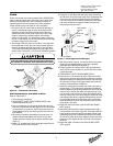
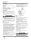
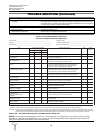
Limit Switch Shaft
Remove any dirt accumulation and spray with a general
purpose lubricant.
Hook Bearing
Apply a few drops of SAE 30 gear or motor oil around the edge
of the bearing.
Idler Sheave Bearing (Bushing)
Disassemble load block and apply a light coat of NLGI #2
grease, or equivalent, inside of bearing.
HOIST REPAIRS
NOTE: If you do not have an experienced mechanic to do your
repair work, we recommend that you send your hoist to an
approved service station for repairs.Use authorized repair
parts only.
1. For major repairs or when the hoist is to be sectioned in the
suspension area, it will be necessary to move the hoist to a
workbench or table.
2. For repairs which can be done by removing the electrical
cover only, the hoist need not be moved.Lowering the hoist
to a convenient working level is desirable.
The following repair instructions will help you in understanding
repair procedures, when related to the Replacement Parts List
starting on page 16. For clarity these are broken down into
areas.
Electrical Parts and Brake
Refer to Figures 9A, 9B & 16.
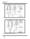
1. Remove the cover to access the controls.Single-phase
models also have a starting switch and capacitor mounted on
the motor as shown in Figure 13.The terminal blocks and end
clamps snap off of the rails on the plate using a small
screwdriver.DO NOT SLIDE THE END CLAMPS.
The reversing contactor can be slid off the rail, but it must be
snapped on.Where the contactor fits the rail, one side has
springs or pads that apply pressure against the edge of the
rail.By pressing against that side at the base of the contactor,
you can snap the part on or off using a rotating action. Note
the numbers that label the terminals on the contactor and
orient the part as shown in Figures 9A & 9B.Single-phase
contactors have a small jumper that is not present on the
3-phase (note the 3 and 5 terminals on the reversing
contactor in Figure 9A).
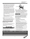
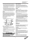
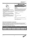
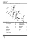
2. Remove the electrical panel by removing the stand-off
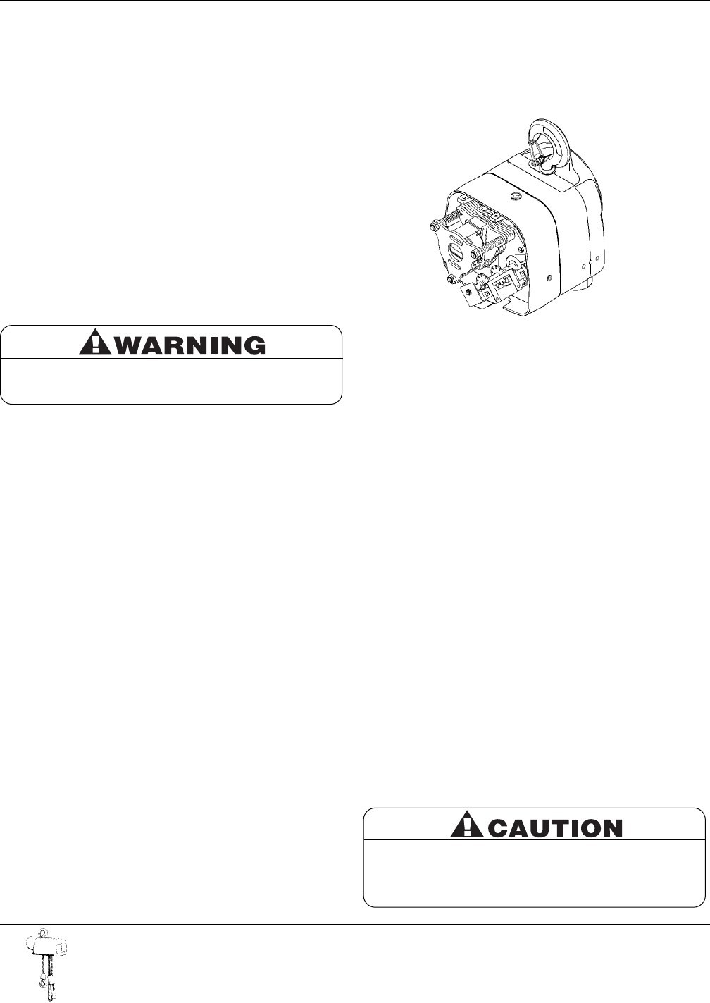
screws (See Figure 16).The limit switch and brake are now
accessible as shown in Figure 7.
3. Remove the transformer bolted to the back of the panel plate
if it requires replacement.
4. Refer to Figure 15 to disassemble the brake.See BRAKE
ADJUSTMENT on page 9 to properly set the brake.
5. Refer to Figure 17 to disassemble the limit switch.
See LIMIT SWITCH ADJUSTMENT on page 8 to properly
set the upper and lower limits of travel.
6. Refer to Figure 18 for repairs on the pushbutton station. Also
refer to the wiring diagram inside the electrical cover or
Figures 9A and 9B for wiring instructions.
Motor
Refer to Figures 12, 13 and 14
The hoist motor is located on the opposite end to that of the
electrical parts, but the two are tied together with electrical
leads running through the housing.
1. If it is necessary to replace or repair the motor,
DISCONNECT THE HOIST FROM THE POWER SUPPLY
and remove the electrical cover.
2. Loosen the screw clamps on the terminal blocks and
reversing contactor to disconnect the motor leads (See
Figure 16).
3. Remove the four motor mounting bolts attaching the motor
to the housing. It will come loose at the motor coupling.
4. Inspect the motor coupling, motor shaft and all the bearings.
Replace as necessary.
5. Install new or repaired motor according to the wiring diagram
located inside the electrical cover or Figures 9A and 9B.
Gearing
Use the Replacement Parts List for Basic Hoist and
Transmission Parts to help in repairs on gearing (See Figures
12 and 19). As disassembly is extensive for gearing,
disconnect hoist and move to a workbench.
1. Remove electrical cover.
2. Remove electrical panel.
3. Remove brake assembly and limit switch assembly.
4. Drain oil from transmission.
10
Milwaukee Electric Tool Corporation
13135 West Lisbon Road
Brookfield, Wisconsin 53005
TEL: (800) 729-3878
Figure 7 - Electrical Panel Removed
Do not disassemble or readjust clutch, or replace with
a clutch assembly from another hoist. Doing so will
void the warranty and may create an unsafe condition.
If replacement is needed due to wear or loss of
adjustment, always use a new clutch assembly.
Remove load and disconnect hoist from power supply
before starting to do any repairs or to take any
sections apart.