


3
MILWAUKEE
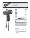
Electric Chain Hoists are rugged, portable hoists
that provide quick, precise lifting.The hoists are constructed of
tough, but lightweight, die cast aluminum alloy housings.An oil
bath transmission, equipped with heat-treated, alloy steel
gears and an overload limiting clutch, provides smooth and
reliable operation.
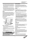
With a pushbutton station that fits comfortably in one hand, the
operator can safely control the hoist while the other hand is
free to guide the load.The electrical controls, which are readily
accessed under the electrical cover, utilize quick connections
for easy voltage conversions and a 24V control circuit for
added safety.
Other features that ensure the safe operation of
MILWAUKEE
Electric Chain Hoists include a magnetic disc brake that
delivers sure stopping and secure holding of the load.
Adjustable upper and lower limit switches regulate the load
travel.As a standard, hooks are supplied with safety latches.
For additional safety, a chain stop is attached to the slack end
of the load chain.
MILWAUKEE
Electric Chain Hoists are designed and tested in
accordance with the American Society of Mechanical
Engineers Code B30.16, “Safety Standard for Overhead
Hoists.” Hoists are built in compliance with CSA, file number
LR 44484. Made in U.S.A.
Milwaukee Electric Tool Corporation
13135 West Lisbon Road
Brookfield, Wisconsin 53005
TEL: (800) 729-3878
TABLE OF CONTENTS
Safety Precautions......................................................................................................................................................................2
Hoist Specifications.....................................................................................................................................................................3
Application Information ...............................................................................................................................................................4
Safety Information.......................................................................................................................................................................4
Installation...................................................................................................................................................................................4
Operation ....................................................................................................................................................................................5
Maintenance ...............................................................................................................................................................................6
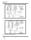
Wiring Diagrams .......................................................................................................................................................................12
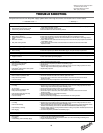
Trouble Shooting.......................................................................................................................................................................13
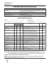
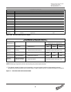
Inspection and Maintenance Check List...................................................................................................................................14
Recommended Lubrication Schedule.......................................................................................................................................15
Replacement Parts List.............................................................................................................................................................16
Parts Depot & Warranty Repair Centers...................................................................................................................................28
Warranty.....................................................................................................................................................................Back Cover
Lifting Control Cord Full Load
Model Capacity Speed Lift Length Reeving HP Voltage Motor Amps
* Phase
(tons) (fpm) (ft) (ft) (AC)
Table 1 - Hoist Specifications
9560 1/2 16 10 6 Single-chained 1/2 115/230V 7.6/3.8 Single
9573 2 8 20 16 Double-chained 1 115/230V 14/7** Single
9570 2 8 10 6 Double-chained 1 115/230V 14/7** Single
9567 1 16 15 11 Single-chained 1 115/230V 14/7** Single
9568 1 16 20 16 Single-chained 1 115/230V 14/7** Single
9566 1 16 10 6 Single-chained 1 230/460V 3.2/1.6 Three
9565 1 16 10 6 Single-chained 1 115/230V 14/7** Single
9562 1/2 16 20 16 Single-chained 1/2 115/230V 7.6/3.8 Single
9561 1/2 16 15 11 Single-chained 1/2 115/230V 7.6/3.8 Single
9572 2 8 15 11 Double-chained 1 115/230V 14/7** Single
9571 2 8 10 6 Double-chained 1 230/460V 3.2/1.6 Three
* At full load, it is not unusual for the hoist to draw in excess of
the values listed when lifting.It is critical to ensure that the
voltage at the hoist contactor does not drop below 10% of
the nominal voltage of the hoist while it is lifting a load.Low
voltage will result in higher amp draw, damage to the hoist,
and potential fire hazards.
MILWAUKEE
is not responsible
for any damages caused by an inadequate power source.
**The 1HP, 115/230V models must have a dedicated power
circuit rated for at least 20A, 125V when they are wired for
115V.It is not unusual for these models to draw up to 20
amps at 115V when lifting at rated capacity. Refer to
Table 3 before installation.
HOIST SPECIFICATIONS