


SECTION TWO - Installation
961 INSTALLATION MANUAL Revision A Page 39
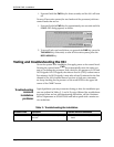
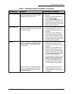
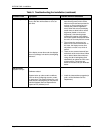
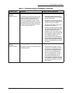
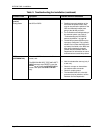
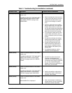
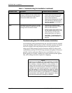
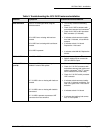
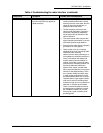
Table 3: Troubleshooting the GPS/DGPS antenna installation
Antenna Symptom Possible Solutions/Reasons
GPS ANTENNA
Poor or no GPS signal while using the
AN150 antenna.
If 5.5 VDC low or missing with load con-
nected:
If 5.5 VDC low is missing with load discon-
nected:
If 5.5 VDC is present:
•
Turn off any onboard transmitting
devices.
•
Check for 5.5 VDC at antenna with
and without antenna load connected.
a
•
Check for 5.5 VDC at 961 processor
BNC connector (1710 board).
•
It indicates a bad connector installa-
tion, bad 1710 board, or bad AN150
antenna.
•
It indicates a bad 1710 board.
Replace the 1710 board.
•
It indicates a bad AN150. Replace the
AN150.
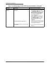
DGPS ANTENNA
No GPS or DGPS
•
Bad splitter configuration.
b
•
Splitter cables may be reversed for
GPS and DGPS output.
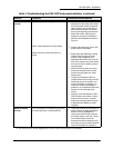
DGPS ANTENNA
(cont’d)
Poor or no GPS signal while using the
AN205-P antenna with splitter:
If 7.75 VDC is low or missing with load con-
nected:
If 7.75 VDC is low or missing with load dis-
connected:
If 7.75 VDC is present at processor UHF
connector but not at antenna:
•
Check installation for correct cabling.
•
Check for 7.75 VDC at antenna with
and without antenna load (cables and
splitter) connected.
c
(Use “T” connec-
tors to measure VDC under load.)
•
Check for 7.75 VDC at 961 processor
UHF connector.
•
It indicates a bad connector installa-
tion, bad 1710 board, bad AN2xx. The
load is too great or the 1710 board is
defective.
•
It indicates a bad 1710 board.
•
It indicates bad cabling, bad connec-
tors, or a bad splitter.