


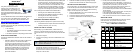
SMART-MR10
™
GM-14915098 Rev 3 Mar/2012
This guide provides the information
required to set up and begin using your
new SMART-MR10, a combined L1+L2
GNSS receiver and antenna, with L-band
support and Emulated Radar (ER) output.
The SMART-MR10 also provides Bluetooth
®
wireless
technology.
For more detailed information on the installation and operation of
your receiver, refer to the SMART-MR10 and OEMV
®
user
manuals, which can be found on the NovAtel Web site at:
www.novatel.com/support/firmware-software-and-manuals/
SMART-MR10 BOX CONTENTS
In addition to this quick start guide, the following are provided
with your SMART-MR10:
• 1 - CD containing:
• An installation program for the NovAtel PC Utilities
• Product documentation
• 1 - User Manual postcard for requesting printed manuals
AVAILABLE ACCESSORIES
The following SMART-MR10 interface cables can be ordered as
accessories:
• Evaluation cable (NovAtel part number 01018515) with
a 23-pin connector on one end and three DB-9
connectors and exposed tinned wires for power, ER,
ground, MKI, MODE, PPS and CAN, on the other. This
cable is designed to allow the rapid deployment and
evaluation of a SMART-MR10 on a construction or
agricultural vehicle. All signals are wired out in this
cable. The evaluation cable is not intended for
permanent installation.
• Streamlined cable (NovAtel part number 01018526) with
two DB-9 connectors, and exposed tinned wires for
power, ground and ER. This cable provides connection
for power, two serial ports, and emulated radar. It has
been designed for permanent installation. The cable
material is capable of withstanding a wide temperature
range and is not damaged by exposure to chemicals.
Four mounting kits are available for the SMART-MR10:
• Mounting Kit, Quick Release Plate (01018625)
• Mounting Kit, Quick Release Assembly (01018578)
• Mounting Kit, AG GPS 262 (01018623)
• Mounting Kit, 5/8 Inch Adapter (01018624)
ADDITIONAL EQUIPMENT REQUIRED
The following additional equipment is required for basic setup:
• A Windows
®
-based computer with an RS-232 DB-9 port.
• A battery connection (+9 to +36 V DC)
INSTALLING THE PC UTILITIES
Before setting up your SMART-MR10, install NovAtel’s PC
Utilities
on the Windows-based computer that you will use to
communicate with it. This computer must have an RS-232 DB-9
port
.
1. Start up the computer.
2. Insert the accompanying CD into the CD-ROM drive of the
computer.
3. Select Install the OEMV PC Utilities from the window that is
automatically displayed. If the window does not
automatically open when the CD is inserted, select Run from
the Start menu and select the Browse button to locate
Setup.exe on the CD drive.
4. Install the PC Utilities by advancing through the steps
provided in the NovAtel GPS PC Utilities setup program.
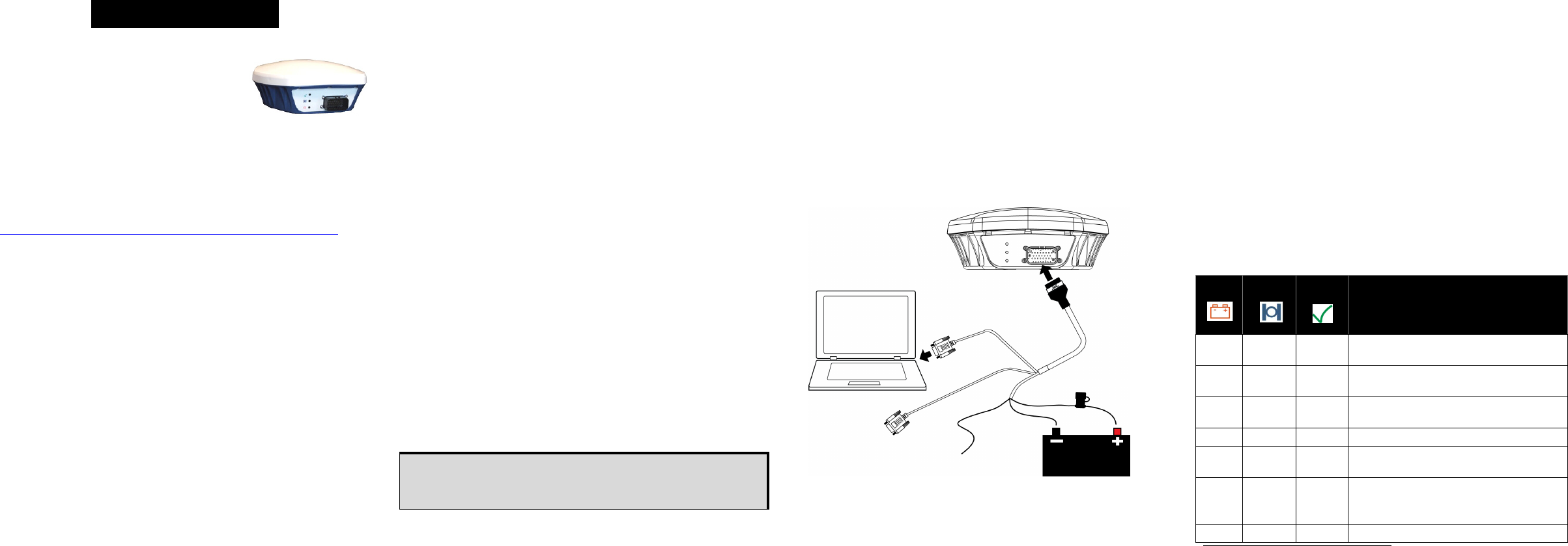
SETTING UP YOUR SMART-MR10
For the basic setup, you need a Windows-based computer with
an RS-232 DB-9 port and NovAtel utilities installed on it, and a
battery connection (+9 to +36 V DC). Complete the following
steps to connect and power your receiver.
1. Mount the SMART-MR10 on a secure, stable structure with
an unobstructed view of the sky.
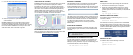
2. Connect the interface cable to the SMART-MR10.
3. Connect the SMART-MR10 to a DB-9 serial port on the
computer.
4. Provide power to the SMART-MR10, as follows.
Connect the red wire of the cable (PWR+, connector pin 1)
to the positive side of a 12 or 24V vehicular power circuit (or
equivalent) that is protected by a 5A fuse. NovAtel
recommends an automotive blade-type fuse, rated for 5A
and with an operating voltage of more than 36V
(recommended fuse part numbers are in the SMART-MR10/
15 User Manual).
Connect the black wire of the cable (PWR-, connector pin 9)
to the negative side of the power circuit.
If a NovAtel supplied SMART-MR10 interface cable is not
used, a minimum wire size of 0.5 mm/ 20AWG is required.
SMART-MR10 LEDS
LEDs on the front of the SMART-MR10 provide basic receiver
status information. The operation of the LEDs on the
SMART-MR10 is summarized in the following table:
QUICK START GUIDE
To access and download the most current version of our
OEMV PC Utilities, go to the Support page of the NovAtel
web site at www.novatel.com.
COM1
COM2
ER
Tyco 23-pin
connector
User supplied
5A fast blow fuse
Table 1: SMART-MR10 LED Behaviour
Red
Yellow
Green
Condition
Off Off Off Power is not available. (Red indicator may also
not be lit if a boot failure has occurred.
On Off Off Power available but no satellites are being
tracked
On
Flashing
a
a. Flashing means that the LED is turning on and off at a 1 Hz rate - 0.5 seconds on
and 0.5 seconds off.
Off Tracking at least one satellite but not a valid
position
On On Off Position valid in basic autonomous mode
On On Flashing SBAS tracking, but not enough data for
enhanced solution.
On On On
Position valid in an enhanced accuracy mode
b
(WAAS/EGNOS/MSAS/DGPS, OmniSTAR
VBS/XP/HP, or RTK)
b. When acting as a reference receiver, all lights on solid indicates a good fixed posi-
tion.
On Flashing Flashing Fixed position with bad integrity