


18W one for this purpose. I use an ordinary Antex 25W iron with a Variac power supply
running at 205V. This seems to work well for me.
All resistors, apart from the special PTC, should be flat against the board surface before
soldering. It is a good idea to use a ‘lead bender’ to preform the leads before putting them into
their places. I use my fingers to do this job, but there are special tools available too. Once the
part is in its holes, bend the leads that stick out the bottom outwards to hold the part in place.
This is called ‘cinching’. Solder from the bottom of the board, applying the solder so that the
hole is filled with enough to spare to make a small cone around the wire lead. Don’t put too
much solder on, and don’t put too little on either. Clip the leads off with a pair of side cutters,
trim level with the top of the little cone of solder.
Once all the resistors have been soldered, quickly check them ALL again. Make sure they are
all soldered and make sure the right values are in the right place.
The diodes can be treated much like resistors. However, they must go in the right way. The
cathode is marked with a band on the body of the device. This must align with the vertical
band on the board. In other words the point of the triangular bit points towards the cathode of
the diode. There are three types of diodes used in this project. Most are ordinary signal diodes,
the 1N4148. You have eight bigger black 1N4004 types. And two zener diodes. When all the
diodes are in place, double check all are pointing the right way.
LED4 and LED6 are mounted vertically into the board. It is a good idea to let them stand off
from the surface of the board a bit. I poke the leads through, and then with about 4mm left
between the bottom of the LED package and the board, I cinch the leads to hold them in place
when the board is upside down. Be careful to get them the right way around.
The polyester capacitors are like little blue or red boxes. Push the part into place up to the
board’s surface. Little lugs on the underside of the capacitor will leave enough of an air gap
for the water wash to work. Cinch and solder the leads as you would resistors.
The smaller electrolytic capacitors are very often supplied with 0.1” lead spacing. My hole
spacing is 0.2”. This means that the underside of these radial capacitors will not go flat onto
the board. This is deliberate, so don’t force the part in too hard. The capacitors will be happy
at around 0.2” above the board, with the legs slightly splayed. Sometimes you will get
electrolytic capacitors supplied with their legs preformed for 0.2” (5mm) insertion. This is
fine, just push them in until they stop. Cinch and solder as before. Make sure you get them in
the right way. Electrolytic capacitors are polarised, and may explode if put in the wrong way.
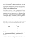
No joke. Oddly, the PCB legend marks the positive side with a ‘+’, although most capacitors
have the ‘-’ marked with a stripe. Obviously, the side marked with a ‘-’ must go in the
opposite hole to the one marked with the ‘+’ sign. Most capacitors usually have a long lead to
depict the positive end as well.
The bigger 1000uF capacitors should be soldered flush onto the board using no-clean or
conventional solder. On no account must these two parts be put in the wrong way.
The transistors all look alike apart from the big TIP31. So look very carefully before inserting
each device. Match the flat side of the device with that shown on the PCB legend. Push the
transistor into place but don’t push too far. Leave about 0.2” (5mm) of the leads visible
15