


underneath the body of transistor. Turn the board over and cinch the two outer leads on the
flip side, you can leave the middle one alone. Now solder the middle pin first, then the other
two once the middle one has cooled solid. Cut off any excess leads.
Sometimes transistors come with the middle leg preformed away from the other two. This is
all right, the part will still fit into the board. However, if I get these parts, I tend to ‘straighten’
the legs out by squashing gently all the three of them flat with a pair of pliers. The flat surface
of the pliers’ jaws parallel to the flat side of the transistor.
The 2SC3381 simply fits into the board with the pins matching up into the holes. You may
need to straighten any bent legs with a pair of pliers. Keep the body of the device about 8 to
10mm above the board surface. Then solder the middle pin. Straighten the device if necessary
and make sure the bottom of it is parallel to the board before soldering the rest of the pins.
If you have been supplied with 2SC1583 instead of the 2SC3381, then you need to be more
careful. The board is laid out for the 3381, and the leads of the 1583 need to be matched up
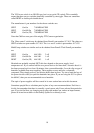
into the correct holes. The 1583 has just five leads, whilst the 3381 has seven. The PCB has
seven holes and they arranged in a staggered fashion on the board to match with the 2SC3381.
Pin1 is on the left hand side, and is designated with a square pad. Pin 2 is staggered below it,
and so on. The format is show below:
1 3 5 7
2 4 6
Hold the 1583 so that its number is facing you and the board has its pots facing you. You need
to fit the 1583 so that the first three pins from left to right go in the first three holes in that
same order. Now ignore the next two holes in the PCB, and fit the remaining two pins into last
two holes on the board.
The quick table shows how the pin numbers match up against each other.
2SC1583 2SC3381
1 1
2 2
3 3
4 6
5 7
The PTC is the special temperature compensating resistor. It should be mounted so that it sits
above the board and rests against the flat face of U6. You’ll need to preform the leads to do
this. Then push the part into the holes marked PTC, solder and cut the leads form the
underside of the PCB. Have a look at the two photographs on the 3031 webpage to see how I
have done it.
For U10 and Q42, the two power devices, it may be necessary to preform the leads before
putting them into the board. I use a pair of fine nosed pliers to bend the middle leg outwards. I
16