


© 2009 Directed Electronics. All rights reserved. 4
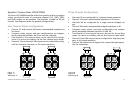
1 2
3 4
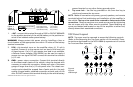
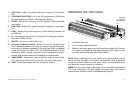
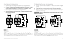
POWER
REM GNDB+
Recommended wire stripping lengths (L):
L (for Power wires): 1.0” (25 mm)
L (for Speaker wires): 0.5” (13 mm)
L (for Remote wires): 0.5” (13 mm)
L
Insulated Wire
+BAT -1. connect this terminal through a FUSE or CIRCUIT BREAKER
to the positive terminal of the vehicle battery or the positive ter-
minal of an isolated audio system battery.
WARNING: Always protect this power wire by installing a fuse or
circuit breaker of the appropriate size within 12 inches of the battery
terminal connection.
REM2. - this terminal turns on the amplifier when (+) 12 volt is
applied. Connect it to the remote turn on lead of the head unit
or signal source. If a (+) 12 volt remote turn lead is not available,
a Remote Power Adapter (P/N ORRPA) can be used to supply a
remote turn on signal. DO NOT connect this terminal to constant
(+) 12 volt.
GND - power return connection. Connect this terminal directly
to the sheet metal chassis of the vehicle, using the shortest wire
necessary to make this connection. Always use wire of the same
gauge or larger than the (+) 12 volt power wire. The chassis con-
nection point should be scraped free of paint and dirt. Use only
quality crimped and/or soldered connectors at both ends of this
wire. DO NOT connect this terminal directly to the vehicle battery
ground terminal or any other factory ground points.
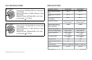
Top cover lock -4.
Use the key provided or the 3mm hex key to
unlock and remove the top cover.
NOTE: Make all connections to power, ground, speakers, and remote
terminals before final positioning and installation of the amplifier in
the vehicle. The top cover needs to be removed to fasten some of the
connections. These connections once made are secured by tightening
the set screws with the Allen wrench provided. These fastening set
screws are labeled and located on top of the amplifier at either end,
directly above their associated connectors.
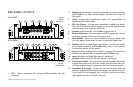
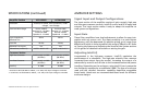
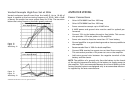
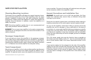
4/00ANEL,AYOUT
NOTE: Top cover must be removed to access the following controls
(Refer to the Removing the Top Cover section of this manual). These
controls are duplicated for the HCCA10004 (a separate set of controls
for Front and Rear channels).
Figure 4
Figura 4
Abbildung 4
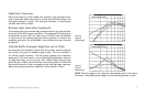
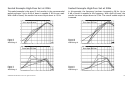
X-OVER
HIGH
PASS
50
HZ
2K
HZ
15
HZ
60
HZ
20
HZ
200
HZ
0
dB
10
dB
50
HZ
2K
HZ
MIN MAX
LOW HIGH
ALL
SLOPE
LOW
PASS
GAIN GAIN
RANGE
OFF
ON
HIGH
LOW
24dB
12dB
INFRASONIC INTELLI-Q
Q FREQ
1 2
3 4
56910 78
Figure 3
Figura 3
Abbildung 3