


© 2009 Directed Electronics. All rights reserved. 4
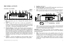
GND -3. Power return connection. Connect this terminal directly
to the sheet metal chassis of the vehicle, using the shortest wire
necessary to make this connection. Always use wire of the same
gauge or larger than the (+) 12 volt power wire. The chassis con-
nection point should be scraped free of paint and dirt. Use only
quality crimped and/or soldered connectors at both ends of this
wire. DO NOT connect this terminal directly to the vehicle battery
ground terminal or any other factory ground points.
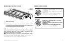
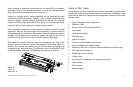
Top cover lock -4. Use the key provided or the 3mm hex key to
unlock and remove the top cover.
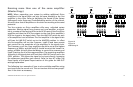
NOTE: Make all connections to power, ground, speakers, and remote
terminals before final positioning and installation of the amplifier in
the vehicle. The top cover needs to be removed to fasten some of the
connections. These connections once made are secured by tightening
the set screws with the Allen wrench provided. These fastening set
screws are labeled and located on top of the amplifier at either end,
directly above their associated connectors.
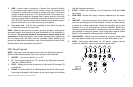
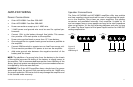
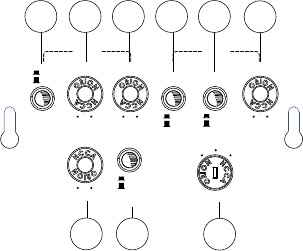
TOP Panel Layout
NOTE: Top cover must be removed to access the following controls
(Refer to the Removing the Top Cover section of this manual).
ON/OFF -1. Turns the intelli-Q on or off.
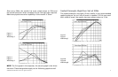
Q -2. Continuously adjusts the “Q” boost of the high-pass crossover
from 0 to 10dB of boost.
FREQ - 3. Adjusts the center frequency of the Intelli-Q between 20
and 200 Hz.
PHASE - 4. Provides either 0 or 180 degree phase shift of the ampli-
fied output (speaker) with respect to the input signal to facilitate
the best bass performance.
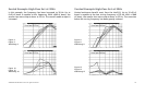
SLOPE -5. Selects the crossover roll off between 12db and 24db
per octave.
LOW PASS -6. Adjusts the upper crossover frequency of the ampli-
fier.
LINE OUT -7. Has three settings: Gain, Master and Copy. This con-
trol is set according to how the amplifier is used, as a stand alone,
a master or a slave respectively. Leave the amplifier set to gain
(default) if it is not connected to another amplifier. When con-
nected in combined amplifier configurations, set to master when
the amplifier is used as a master, set to copy when used as a slave
(Refer to the Amplifier Wiring section of this manual).
GAIN RANGE - 8. Selects the input sensitivity range to either High
(for high power head units) or Low (for line level head units).
GAIN - 9. Continuous adjustment for full power output used to
match the amplifier input to the source output level.
Figure 3
Figura 3
Abbildung 3
INTELLI-Q X-OVER
Q
0
dB
10
dB
MIN MAX
FREQ
SLOPE
GAIN
PHASE
LOW PASS
GAIN
COPYMASTER
LINE OUT
GAIN
RANGE
20
HZ
200
HZ
20
HZ
300
HZ
ON
OFF
180°
0°
HIGH
LOW
24dB
12dB
1 2
3
4
6
5
9
7
8