


CQ-5302U
47
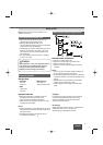
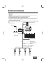
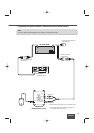
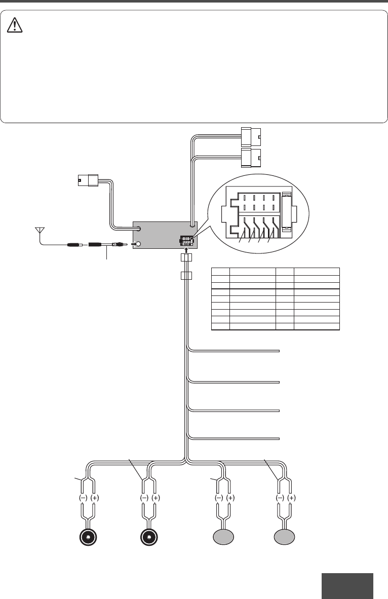
Electrical Connections
Caution
• This wiring information is for experienced technical individual, for safety reason, please your dealer wire this
connection.
• This product is designed to operate with a 12 V DC, negative ground battery system.
• To prevent damage to the unit, be sure to follow the connection diagram below.
• Do not insert the power connector into the unit until the wiring is completed.
• Be sure to insulate any exposed wires from a possible short-circuit from the vehicle chassis. Bundle all cables and
keep cable terminals free from touching any metal parts.
• Remember, if your vehicle has a drive computer or a navigation computer, the data of its memory maybe erased
when the battery terminals are disconnected.
(Rear Side)
CD Receiver
CQ-5302U
Antenna
Wired remote
connector
ቪ Antenna Connector
Accessory Power(ACC)
(+12V DC, negative ground
only)
CD changer control connector
XM/SIRIUS control connector
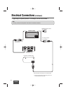
Ground Lead
(Connect to a clean, bare
metallic part of your vehicle)
Battery Lead
(Connect to vehicle battery)
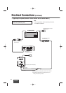
(Red)
ACC
Ground
(Black)
(Yellow)
Battery
Illumination Lead
(Not used)
(Orange)
Illumination
(Violet)
(Violet/Black)
(Gray/Black)
(Green)
(Green/Black)
(White/Black)
(Gray)(white)
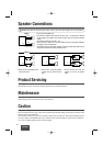
Left Speaker
(Front)
Right Speaker
(Front)
Left Speaker
(Rear)
Right Speaker
(Rear)
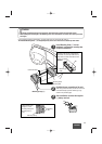
Power Connector
The power connector does not come
along with the unit. If need, please
consult your dealer.
Detail of power connector
NO. FUNCTION NO. FUNCTION
1BATTERY +12 V 9 REAR SP R (–)
2 GROUND 10 REAR SP R (+)
3 ůůůů 11 FRONT SP R (–)
4 ůůůů 12 FRONT SP R (+)
5 ůůůů 13 FRONT SP L (–)
6 POWER +12 V ACC 14 FRONT SP L (+)
7 ůůůů 15 REAR SP L (–)
8 ůůůů 16 REAR SP L (+)
※
10 12 14 16
7
8642
531
9111315
❐ Wiring Diagram