


❐ Preparation
• Disconnect the cable from the negative battery
terminal (see warning and caution below).
• Remove Mounting Collar q and Trim Plate u from the
main unit temporarily, which are already mounted at
shipment.*
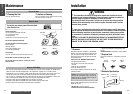
• Unit should be installed in a horizontal position with the
front end up at a convenient angle, but not more than 30°.
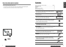
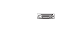
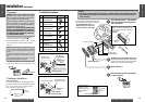
❐ Dashboard Installation
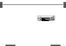
Installation Opening
This unit can be installed in any dashboard having
an opening as shown below. The dashboard should
be 3 ⁄ 16" (4.75 mm)–7 ⁄ 32" (5.56 mm) thick in
order to be able to support the unit.
17
E
N
G
L
I
S
H
18
E
N
G
L
I
S
H
2928
CQ-C1200U/C1120U/C1110U/C1100U CQ-C1200U/C1120U/C1110U/C1100U
Cautions:
¡We strongly recommend that you wear gloves for installation work to protect yourself from injuries.
¡
When bending the mounting tab of the mounting collar with a screwdriver, be careful not to injure your
hands and fingers.
1
2
3
4
Mounting Holes
t Mounting Bolt
Insert Trim Plate u.
After installation reconnect the negative
(–) battery terminal.
First complete the electrical connections, and
then check them for correctness.(
a page 30)
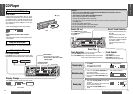
The included Mounting Collar q is
designed specially for this unit. Do
not use it to attach any other model.
Mounting Springs (
C)
y Power Connector
Engage the Mounting
Springs (
C) in the
mounting holes of the
Mounting Collar q
firmly.
Mounting Spring
Mounting
Hole
Insert Mounting Collar q into the dash-
board, and bend the mounting tabs out
with a screwdriver.
The tabs to be bent vary depending on
the car. To securely install the unit, fully
bend a number of the tabs so that there
is no rattling.
Example:
Tab
q Mounting
Collar
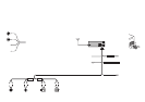
(a) Using the rear support strap e
r Tapping screw
(5 mmø×16 mm)
w Hex. nut
(5 mmø)
e Rear support strap
t Mounting bolt (5 mmø)
q Mounting collar
Fire wall of car
3 mmø
(b) Using the rubber cushion (option)
t Mounting bolt
(5 mmø)
q Mounting collar
Rear support bracket
(provided on the car)
Rubber cushion (option)
Establish the rear connection of the unit.
After fixing Mounting Bolt t and Power Connector
y, fix the rear of the unit to the car body by either
method (a) or (b) shown the previous page.
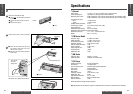
Installation (Continued)
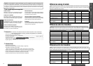
❐ Installation Hardware
i
Dismounting Plate
(YFX214C323ZA)
1
2
Less than 30°
Caution: Various settings that have been stored in the
memory in other on-board equipment (car navigation
etc.) may be lost if the battery terminals are discon-
nected.
Therefore, we recommend to make a record of or to
back up the settings before disconnecting the termi-
nals.
After completing installation of the main unit, set the
equipment again according to the record.
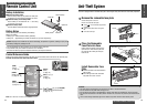
Warning: If your car is equipped with air bag
and/or anti-theft systems, specific procedures
may be required for connection and disconnec-
tion of the battery to install this product.
Before attempting installation of this electronic
component, contact your car dealer or manufac-
turer to determine the required procedure and
strictly follow their instructions.
FAILURE TO FOLLOW THE PROCEDURE MAY
RESULT IN THE UNINTENDED DEPLOYMENT OF
AIR BAGS OR ACTIVATION OF THE ANTI-THEFT
SYSTEM RESULTING IN DAMAGE TO THE VEHI-
CLE AND PERSONAL INJURY.
ItemNo. Diagram Q’ty
t
y
u
Mounting Collar*
(FX0214C316ZA)
Hex. nut (5 mmø)
(YJN994C002ZA)
Rear support strap
(YFG044C002ZA)
Tapping screw (5 mmø×16 mm)
(XTT5+16AFK)
Mounting Bolt (5 mmø)
(YEJV014C002A)
Power Connector
(YEAJ02877)
Trim Plate*
(YFC054C063ZA)
1
1
1
1
1
1
q
w
e
r
(182 mm)
(53 mm)
7
5
/
32
"
2
3
/
32
"