


E
N
G
L
I
S
H
20
CQ-DF701W
29
E
N
G
L
I
S
H
19
Installation Guide
CQ-DF701W
28
1
1
1
1
1
1
1
1
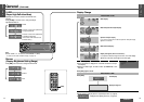
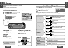
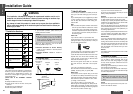
No. Item Diagram Q’ty
WARNING
This installation information is designed for experienced installers and is not in-
tended for non-technical individuals. It does not contain warnings or cautions of po-
tential dangers involved in attempting to install this product.
Any attempt to install this product in a motor car by anyone other than qualified in-
staller could cause damage to the electrical system and could result in serious per-
sonal injury or death.
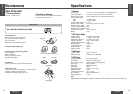
❐ Installation Hardware
If you encounter problems, please consult your
nearest professional installer.
6
7
8
Mounting collar
Hex. nut (5 mm·)
Rear support strap
Tapping screw
(5 mm·a16 mm)
Mounting bolt (5 mm·)
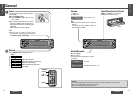
Power connector
Removable face plate
case
Trim plate
1
2
3
4
5
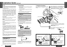
❐ Overview
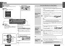
12 V DC
Test bulb
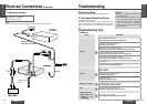
Electrical
tape
Side-cut
pliers
❐ Required Tools
You’ll need a screwdriver, a 1.5 V AA battery, and
the following:
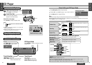
❐ Dashboard Specifications
Thickness
Min. 4.75 mm
Max. 5.56 mm
53 mm
182 mm
This product should be installed by a professional.
However, if you plan to install this product yourself,
your first step is to decide where to install it. The
instructions in these pages will guide you through
the remaining steps:
(Please refer to the “WARNING” statement
above.)
≥Identify and label the car wires.
≥Connect the car wires to the wires of the power
connector.
≥Install the unit in the dashboard.
≥Check the operation of the unit.
Caution:
≥This unit operates with a 12 V DC negative
ground auto battery system only. Do not at-
tempt to use it in any other system. Doing so
could cause serious damage.
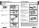
Before you begin installation, look for the items
which are packed with your unit.
≥Panasonic Servicenter for Service Directory
…Keep for future reference in case the product
needs servicing.
≥Installation Hardware…Needed for in-dash in-
stallation.
The first step in installation is to identify all the car
wires you’ll use when hooking up your sound sys-
tem.
As you identify each wire, we suggest that you label
it using masking tape and a permanent marker.
This will help avoid confusion when making con-
nections later.
Note:
≥Do not connect the power connector to the stereo
unit until you have made all connections. If there
are no plastic caps on the stereo hooking wires,
insulate all exposed leads with electrical tape until
you are ready to use them. Identify the leads in
the following order.
Power Lead
If your car has a radio or is pre-wired for one:
Cut the connector wires one at a time from the plug
(leaving the leads as long as possible) so that you
can work with individual leads.
❐ Identify All Leads
Turn the ignition on to the accessory position, and
ground one lead of the test bulb to the chassis.
Touch the other lead of the test bulb to each of the
exposed wires from the cut radio connector plug.
Touch one wire at a time until you find the outlet
that causes the test bulb to light.
Now turn the ignition off and then on. If the bulb
also turns off and on, that outlet is the car power
lead.
If your car is not wired for an audio unit:
Go to the fuse block and find the fuse port for radio
(RADIO), accessory (ACC), or ignition (IGN).
Battery Lead
If your stereo unit has a yellow lead, you will need
to locate the car’s battery lead. Otherwise you may
ignore this procedure. (The yellow battery lead pro-
vides continuous power to maintain a clock, memo-
ry storage, or other function.)
If your car has a radio or is pre-wired for one:
With the ignition and headlights off, identify the car
battery lead by grounding one lead of the test bulb
to the chassis and checking the remaining exposed
wires from the cut radio connector plug.
If your car is not wired for an audio unit:
Go to the fuse block and find the fuse port for the
battery, usually marked BAT.
Speakers
Identify the car speaker leads. There are two leads
for each speaker which are usually color coded.
A handy way to identify the speaker leads and the
speaker they are connected with is to test the leads
using a 1.5 V AA battery as follows.
Hold one lead against one pole of the battery and
stroke the other lead across the other pole. You will
hear a scraping sound in one of the speakers if you
are holding a speaker lead.
If not, keep testing different lead combinations until
you have located all the speaker leads. When you
label them, include the speaker location for each.
Antenna Motor
If your car is equipped with an automatic power an-
tenna, identify the car motor antenna lead by con-
necting one bulb tester lead to the car battery lead
and touching the remaining exposed wires from the
cut radio connector plug one at a time. You will
hear the antenna motor activate when you touch
the correct wire.
Antenna
The antenna lead is a thick, black wire with a metal
plug at the end.
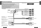
❐ Connect All Leads
Now that you have identified all the wires in the car,
you are ready to begin connecting them to the
stereo unit wires. The wiring diagram (➡ pages
34j35) shows the proper connections and color
coding of the leads.
We strongly recommend that you test the unit be-
fore making a final installation.
You can set the unit on the floor and make tempo-
rary connections to test the unit. Use electrical tape
to cover all exposed wires.
Important:
≥Connect the red power lead last, after you
have made and insulated all other connec-
tions.
Ground
Connect the black ground lead of the power con-
nector to the metal car chassis.