


E
N
G
L
I
S
H
CQ-DFX572U
55
E
N
G
L
I
S
H
39
CQ-DFX572U
54
E
N
G
L
I
S
H
40
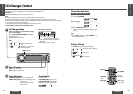
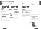
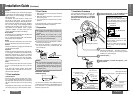
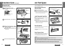
First complete the electrical connections, and
then check them for correctness. (➡ page 58)
The included mounting collar 1 is designed
specially for this unit. Do not use it to attach
any other model.
6 Power connector
Mounting tabs
5 Mounting bolt (5 mm·)
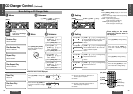
❐ Installation Procedures
Insert mounting collar 1 into the dashboard, and
bend the mounting tabs out with a screwdriver.
(a) Using the rear support strap 3
4 Tapping screw
(5 mm·a16 mm)
2 Hex. nut
(5 mm·)
3 Rear support
strap
5 Mounting bolt
(5 mm·)
1 Mounting collar
Fire wall of car
3 mm·
(b) Using the rubber cushion (option)
5 Mounting bolt
(5 mm·)
1 Mounting collar
Rear support bracket
(provided on the car)
Rubber cushion (option)
1
Secure the rear of the unit.
After fixing mounting bolt
5
and power connector
6
,
fix the rear of the unit to the car body by either
method (a) or (b) shown below.
Insert trim plate 8.
After installation, reconnect the negative - bat-
tery terminal.
2
3
4
Tab
Tab
Dashboard
Mounting collar
1
Fastening the mounting collar
The tabs to be bent vary depending on
the car. Bend them with a screwdriver
to fasten the mounting collar
1
secure-
ly in the dashboard.
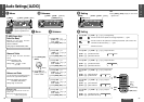
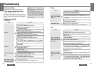
Installation Guide (Continued)
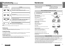
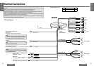
Speakers
Connect the speaker wires. See the wiring diagram
(➡ page 58) for the proper hookups. Follow the di-
agram carefully to avoid damaging the speakers
and the stereo unit.
The speakers used must be able to handle more
than 50 W of audio power. If using an optional
audio amplifier, the speakers should be able to han-
dle the maximum amplifier output power. Speakers
with low input ratings can be damaged. Speaker
impedance should measure 4–8 ≠, which is typi-
cally marked on most speakers. Lower or higher
impedance speakers will affect output and can
cause both speaker and stereo unit damage.
Motor Antenna
Connect the car motor antenna lead to the dark blue
motor antenna relay control lead.
(Do not confuse the antenna lead with blue/white
stripe lead for a power amplifier.)
Battery
Connect the yellow battery lead to the correct radio
wire or to the battery fuse port on the fuse block.
Antenna
Connect the antenna by plugging the antenna lead
into the antenna receptacle.
Equipment
Connect any optional equipment such as an amplifi-
er, according to the instructions furnished with the
equipment. Leave about 12z (30 cm) of distance
between the speaker leads/amplifier unit and the
antenna/antenna extension cord. Read the operat-
ing and installation instructions of any equipment
you will connect to this unit.
Power
Connect the red power lead to the correct car radio
wire or to the appropriate fuse port on the fuse
block.
If the stereo unit functions properly with all these
connections made, disconnect the wires and pro-
ceed to the final installation.
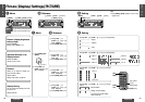
❐ Final Installation
❐ Final Checks
Lead Connections
Connect all wires, making sure that each connec-
tion is insulated and secure. Bundle all loose wires
and fasten them with tape so they will not fall down
later. Now insert the stereo unit into the mounting
collar.
Congratulations! After making a few final checks,
you’re ready to enjoy your new auto stereo system.
1. Make sure that all wires are properly connected
and insulated.
2. Make sure that the stereo unit is securely held in
the mounting collar.
3. Turn on the ignition to check the unit for proper
operation.
If you have difficulties, consult your nearest author-
ized professional installer for assistance.
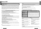
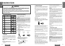
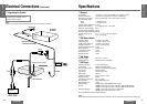
❐ Preparation
≥We strongly recommend that you wear gloves
for installation work to protect yourself from
injuries.
≥When bending the mounting tabs of the
mounting collar with a screwdriver, be careful
not to injure your hands and fingers.
≥Disconnect the cable from the negative
-
battery
terminal (see caution below).
≥Unit should be installed in a horizontal position
with the front end up at a convenient angle, but
not more than 30o.
Caution:
≥Do not disconnect the battery terminals of a
car with a trip or navigational computer since
all user settings stored in memory will be lost.
Instead take extra care with installing the unit
to prevent shorts.
Less than 30x
Dashboard Installation
Installation Opening
(182 mm)
(53 mm)
7
5
/
32
q
2
3
/
32
q
This unit can be installed in any dashboard having
an opening as shown above. The dashboard should
be
3
⁄16z (4.75 mm)j
7
⁄32z (5.56 mm) thick in order to
be able to support the unit.
Note:
≥To securely install the unit, fully
bend a number of the tabs so that
there is no rattling.
≥Be sure to fasten the unit securely
when joining it with the mounting
collar
1
.