


E
N
G
L
I
S
H
CQ-DFX572U
57
E
N
G
L
I
S
H
41
CQ-DFX572U
56
E
N
G
L
I
S
H
42
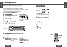
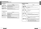
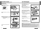
Anti-Theft System
Security Indicator
The security indicator blinks when the removable
face plate is removed from the unit.
Active the security function in the function settings.
(➡ page 40)
Panel Removal Alarm
This alarm sounds to warn you not to forget to re-
move the panel before leaving your car. This func-
tion is activated when the security indicator is on.
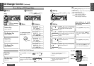
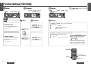
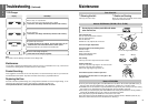
Install Removable Face Plate
1 Fit the face plate with its left hole on one of the
pins provided on the main unit.
2 Fit the other hold on the other pin applying
slight pressure.
3 Move the face plate up and down a few times to
make sure it is secure. Then close the front
panel and press down the right side of the face
plate until it clicks into plate.
Caution:
≥This face plate is not waterproof. Do not expose it to water or excessive moisture.
≥Do not remove the face plate while driving your car.
≥Do not place the face plate on the dashboard or nearby areas where the temperature rises to high level.
≥Do not touch the contacts on the face plate or the main unit, since this may result in poor electrical con-
tacts.
≥If dirt or other foreign substances get on the contacts, wipe them off with a clean and dry cloth.
≥To avoid damaging the front panel, do not push it down or place objects on it while it is open.
This unit is equipped with a removable face plate. Removing this face plate makes the radio totally inoperable.
The security indicator will blink.
Place the Removable Face
Plate into Case
1 Switch off the power of the unit.
2 Remove the removable face plate. (➡ page 56)
3 Gently press the bottom of the case and open
the cover. Place the face plate into the case and
take it with you when you leave the car.
1
2
3
7 Removable face plate case
Security indicator
Contact
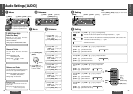
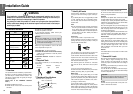
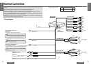
Installation Guide (Continued)
Remove the removable face plate.
1 Press [OPEN]. The removable face plate will
be opened.
2 Push the face plate to the left.
3 Pull it out toward you.
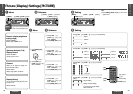
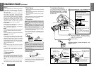
Remove the Unit
Screwdriver
8 Trim plate
Remove the trim plate 8 with a screwdriver.
1 Insert the lock cancel plates 9 along the
grooves on both sides of the main unit
until “click” is heard.
2 Pull out the unit while pushing the plates
further inside.
Remove the unit pulling with both hands.
1
2
3
4
1 Open
2 Push
3 Pull out
Contact
Main unit
Switch off the power of the unit.
9 Lock cancel plate
P
.
SET/DISC
N
5
O
6
W
;
/ 1
OPEN
BAND
TUNE
TRACK
SET/APM
[OPEN]
OSFET
50W
X
4
“Click”
1 Insert
2 Pull out
Insert the tab
end in the
outer groove.