


.-:
..
'
------_._~------~
....
_-,,--_._.-~--'-'-,._.'---"
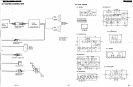
Fig
~
t
~
7'.!
. r
18
:=t
~
:Jt
•
WAVE
f
.AM
RF
®-€
!
~
---,~-.,-
.,
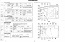
Fig.
14
•••
' •
.1
Lever
Fig.
13
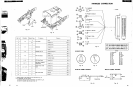
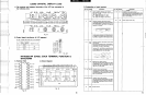
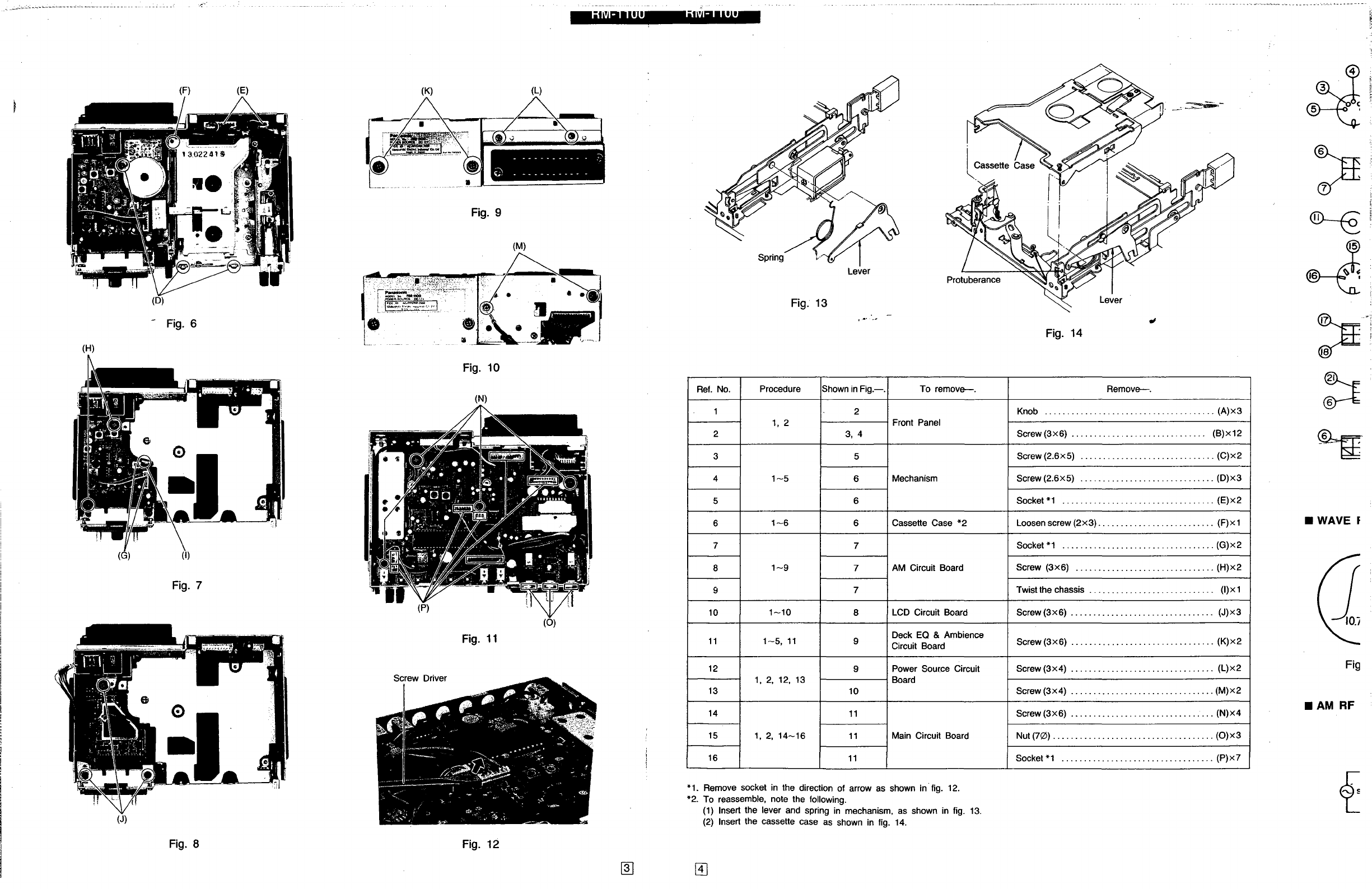
Ref.
No.
Procedure Shown
in
Fig.-.
To
remove-.
Remove-.
1 2
Knob
......................................
(A)x3
1,
2
Front Panel
2
3,4
Screw(3x6)
...........
,
..................
(B)x12
3 5
Screw
(2.6x5)
..............................
(C)x2
4
1-5
6
Mechanism
Screw
(2.6x5)
..............................
(D)x3
5 6
Socket
*1
..................................
(E)x2
6
1-6
6 Cassette Case
*2
Loosen screw
(2x3)
.
.........................
(F)x1
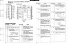
7
7
Socket
*1
.......................
,
..........
(G)x2
8
1-9
7
AM
Circuit Board
Screw
(3x6)
...............................
(H)x2
9
7
Twistthe chassis
............................
(I)x1
10
1-10
8
LCD
Circuit Board Screw
(3x6)
................................
(J)x3
11
1-5,
11
9
Deck
EO
& Ambience
Screw(3x6)
................................
(K)x2
Circuit Board
12
9
Power
Sour.ce
Circuit
Screw
(3x4)
................................
(L)x2
1,
2,
12,
13
Board
13
10
Screw
(3x4)
................................
(M)x2
14
11
Screw
(3x6)
.............
,
..................
(N)x4
15
1,2,
14-16
11
Main Circuit Board Nut
(70)
....................................
(0)x3
16
11
Socket
*1
..................................
(P)x7
*1. Remove socket
in
the direction of arrow
as
shown
in
fig.
12.
*2.
To
reassemble, note the following.
(1)
Insert the lever
and
spring
in
mechanism,
as
shown
in
fig.
13.
(2)
Insert the cassette case
as
shown
in
fig.
14.
•
__
.
._._
...
' 0
~)
'.
. - - -- - - - -
_.
-
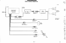
(L)
(M)
(0)
(N)
Fig. 9
.J.
I
Fig.
10
Fig.
11
(K)
(E)
(I)
(F)
Fig.
7
(D)
-
Fig.
6
(G)
(J)
(H)
Fig.
8
Fig. 12
@]
@]