


Pelco Manual C939M-D (7/00) 5
4. Insert the enclosure cable through the feedthrough gland at the base of the receiver.
Connect to terminal strip. Enclosure voltage is always the same voltage as the input volt-
age to the receiver.
5. Replace the protective shield over the terminal strip and reinstall the PC board.
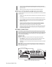
ERD97P-AUX, OPTION BOARD (ALARMS AND AUXILIARIES)
To install the ERD97P-AUX board, do the following. If the ERD97P-AUX is already installed,
proceed to step 4.
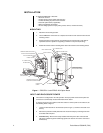
1. Locate P7, the 16-pin female connector located on the main board of the receiver. Re-
fer to Figure 1.
2. Insert the male connector, located on the bottom of the ERD97P-AUX board, into P7.
3. Secure the ERD97P-AUX board to the main PC board with three Phillips head screws
and lock washers. (The three screws and lock washers were packaged with the
ERD97P21-U Receiver.)
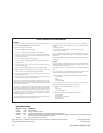
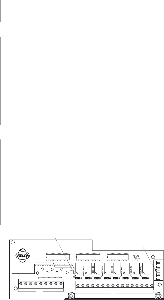
4. (Optional) The auxiliary switches are factory set for remote (keyboard) operation.
The option board’s auxiliary functions can be controlled manually by resetting the
Manual Auxiliary Control switches to the ON position. Refer to Figure 2.
5. (Optional) The auxiliary output relays are factory set in the normally open (NO) position.
To reset the auxiliary output relays to normally closed mode, change the jumpers to
the NC position. Refer to Figure 2.
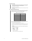
EQUIPMENT CONNECTIONS
All connections to the PC board and option board are made through easy-to-use terminal
strips. To make equipment connections, thread cable/wire through the feedthrough glands
located on the base of the receiver. Refer to the Wiring Table (located on the inside lid of the
receiver) and the printed labeling on the circuit boards. Use a small, slotted screwdriver to
connect wires to the terminal strip.
WIRING TIPS
Pan/Tilt –The ERD9721-U has two connections for wiring pan/tilt preset operation.
a. SL/PP Models – Wire Pan A to the pan/tilt connection that is labeled “SL (360°)
Preset.” Wire Pan B to the pan/tilt connection that is labeled “Pan Preset.”
b. PP Models – Pan A is not used. Wire Pan B to the pan/tilt connection that is labeled
“Pan Preset.”
Alarm Inputs – The main PC board has one alarm input, which is normally open. The
ERD970-AUX option board provides an additional eight alarm inputs (normally open), as
well as eight auxiliary outputs.
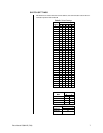
Figure 2. ERD97-AUX Option Board Layout
GND 2 3 4 5 6 7 8 9
ALARMS
P9
1+ 1- 2+ 2- 3+ 3- 4+ 4-
AUX
5+ 5- 6+ 6- 7+ 7- 8+ 8-
P11
P8
NO NC
RN1
C5
C6
C8
C7
C1
C2
C4
C3
RN2
RN3
K8 K7 K6 K5 K4 K3 K2 K1
NO NC NO NC NO NC NO NC NO NC NO NC NO NC
D8
D7
D6
D5
D4
D3
D2
D1
C9
U3
U2
U1
ON
12357648
P1
RELAY OUTPUT JUMPERS
MANUAL AUXILIARY
CONTROL SWITCHES