


6 Pelco Manual C939M-D (7/00)
JUMPER SETTINGS
1. RX Termination – To daisy chain receivers (connect two or more receivers together),
reset the RX Termination jumper to the non-terminating position. The last receiver in
the daisy chain is the terminating unit, do not reset the jumper.
2. TX Termination – Not applicable.
3. Alarm Out – The ERD9721-U alarm output can be set for normally open or normally
closed operation.
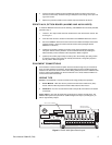
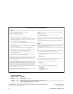
VOLTAGE AND FUSING OPTIONS
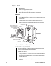
The ERD97P21-U Receiver can be configured to operate at 24 VAC, 120 VAC, or 230 VAC.
Seven plug-in connectors and nine fuses are included with the ERD97P21-U Receiver.
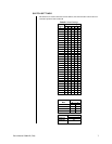
Install the proper voltage cubes and fuses. Refer to Table A and Figure 1.
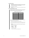
Table A. Voltage Cubes and Fuses
Voltage Input Cube Fuse
Power 24V 5A Slow Blow
Power 120V (Installed) 2A Slow Blow (Installed)
Power 230V 1A Slow Blow
Camera Power 24V (Installed) 1A (Installed)
Camera Power 120/230V .2A or 1/16A
Pan/Tilt Power 24V None
Pan/Tilt Power 120/230V None
1.5A (Enclosure)*
3A (Enclosure)*
5A (Enclosure)*
*The receiver comes with three enclosure fuses (1.5A, 3A and 5A). Select the appropriate
value for your application using the following steps:
1. Determine the full-load wattage requirements of the enclosure.
2. Divide the enclosure wattage determined in step 1 by the input voltage to the receiver.
3. Select a fuse value that is close to, but not less than, the value determined in step 2.
Example:
An environmental enclosure with 120 VAC input, heater, defroster and window wiper.
From the enclosure specifications:
Heater ................... 160 watts
Defroster ............... 15 watts
Window Wiper ....... 90 watts
Total wattage ......... 265 watts
265/120 VAC = 2.208 Amps
Therefore, a 3A fuse will work for this sample enclosure.