


2002 Mar 05 9
Philips Semiconductors Product specification
4 × 40 W BTL quad car radio power
amplifier
TDA8571J
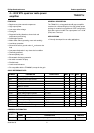
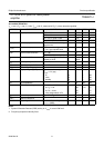
AC CHARACTERISTICS
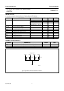
V
P
= 14.4 V; R
L
=4Ω; f = 1 kHz; T
amb
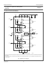
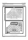
=25°C; measured in Fig.7; unless otherwise specified.
Notes
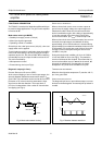
1. Dynamic Distortion Detector (DDD) active, pin V
DIAG
is set to LOW level.
2. Frequency response externally fixed.
SYMBOL PARAMETER CONDITIONS MIN. TYP. MAX. UNIT
P
o
output power THD = 0.5% 16 19 − W
THD = 10% 21 26 − W
V
P
= 13.7 V; THD = 0.5% − 17.5 − W
V
P
= 13.7 V; THD = 10% − 23 − W
P
o(EIAJ)
EIAJ output power THD = maximum;V
i
= 2 V (p-p)
square wave
35 40 − W
P
o(max)
maximum output power THD = maximum; V
P
= 15.2 V;
V
i
= 2 V (p-p) square wave
40 45 − W
THD total harmonic distortion P
o
=1W − 0.1 − %
V
MODE
= 0.6 V; note 1 − 10 − %
B
p
power bandwidth THD = 0.5%; P
o
= −1 dB with
respect to 16 W
− 20 to
20000
− Hz
f
ro(l)
low frequency roll-off at −1 dB; note 2 − 25 − Hz
f
ro(h)
high frequency roll-off at −1dB 20 −−kHz
G
v(cl)
closed-loop voltage gain 33 34 35 dB
SVRR supply voltage ripple rejection R
s
=0Ω; maximum ripple
V
ripple
= 2 V (p-p)
on 40 −−dB
mute 50 −−dB
standby 80 −−dB
Z
i
input impedance 25 30 38 kΩ
V
n(o)
noise output voltage B = 20 Hz to 20 kHz
on; R
s
=0Ω−125 170 µV
on; R
s
=10kΩ−150 −µV
mute; independent of R
s
− 100 −µV
α
cs
channel separation P
o
= 16 W; R
s
=10kΩ 45 −−dB
∆G
v
channel unbalance −−1dB
V
o
output signal in mute maximum input voltage
V
i
= 1 V (RMS)
−−2mV