


INSTALLATION MANUAL
MANUEL D’INSTALLATION
<KYMFF/01D00000>
AVX-7300
Printed in Japan
Imprimé au Japon
<CRD3482-A> UC
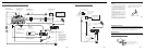
Connecting the Units <ENGLISH>
Note:
• This unit is for vehicles with a 12-volt battery and
negative grounding. Before installing it in a recre-
ational vehicle, truck, or bus, check the battery
voltage.
• To avoid shorts in the electrical system, be sure to
disconnect the ≠ battery cable before beginning
installation.
• Refer to the owner’s manual for details on
connecting the power amp and other units, then
make connections correctly.
• Secure the wiring with cable clamps or adhesive
tape. To protect the wiring, wrap adhesive tape
around them where they lie against metal parts.
• Route and secure all wiring so it cannot touch any
moving parts, such as the gear shift, handbrake and
seat rails. Do not route wiring in places that get
hot, such as near the heater outlet. If the insulation
of the wiring melts or gets torn, there is a danger of
the wiring short-circuiting to the vehicle body.
• Don’t pass the yellow lead through a hole into the
engine compartment to connect to the battery. This
will damage the lead insulation and cause a very
dangerous short.
• Do not shorten any leads. If you do, the protection
circuit may fail to work when it should.
• Never feed power to other equipment by cutting
the insulation of the power supply lead of the unit
and tapping into the lead. The current capacity of
the lead will be exceeded, causing overheating.
• When replacing fuse, be sure to use only fuse of
the rating prescribed on the fuse holder.
• If the RCA pin jack on the unit will not be used, do
not remove the caps attached to the end of the con-
nector.
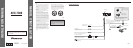
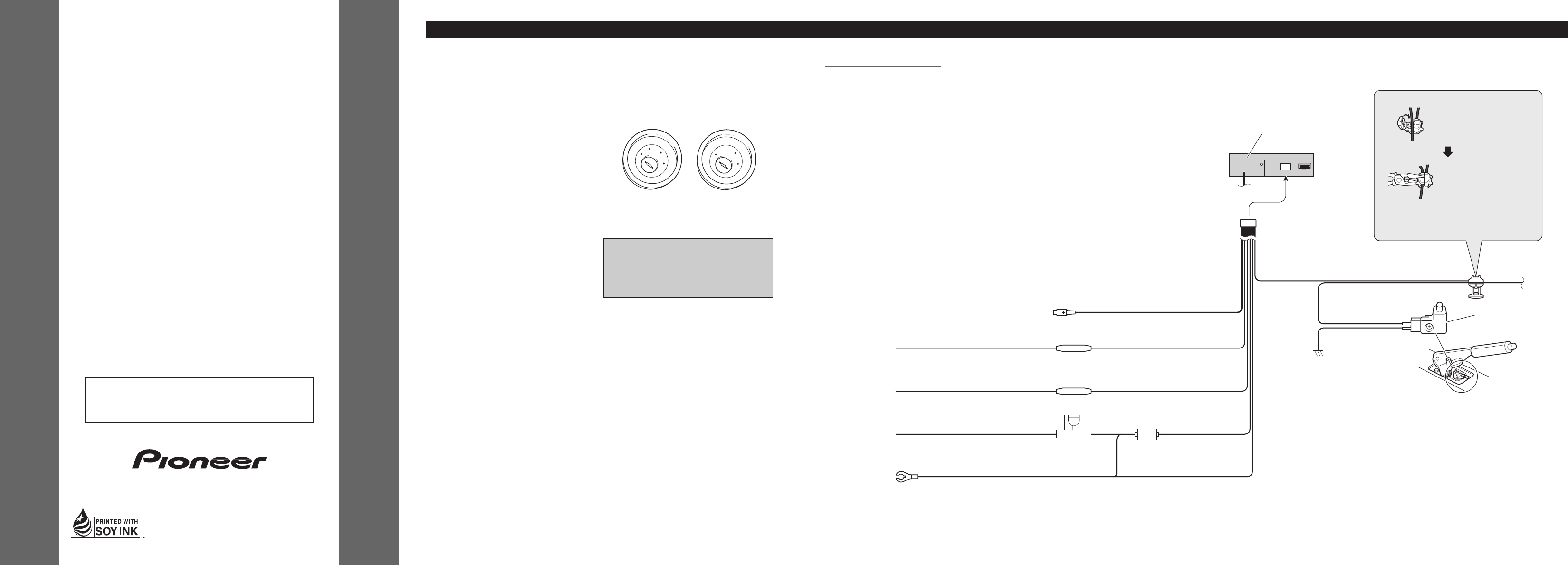
• If this unit is installed in a vehicle that does not
have an ACC (accessory) position on the ignition
switch, the red lead of the unit should be connected
to a terminal coupled with ignition switch ON/OFF
operations. If this is not done, the vehicle battery
may be drained when you are away from the vehi-
cle for several hours. (Fig.1)
Fig. 1
No ACC positionACC position
O
N
S
T
A
R
T
O
F
F
A
C
C
O
N
S
T
A
R
T
O
F
F
This product conforms to CEMA cord colors.
Le code de couleur des câbles utilisé pour ce produit est
conforme à CEMA.
• Cords for this product and those for other products
may be different colors even if they have the same
function. When connecting this product to another
product, refer to the supplied Installation manuals
of both products and connect cords that have the
same function.
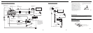
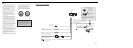
Light green
Used to detect the ON/OFF status of the parking brake.
This lead must be connected to the power supply side
of the parking brake switch.
Parking brake switch
Red
To electric terminal controlled by ignition
switch (12 V DC) ON/OFF.
Fuse resistor
Fuse holder
Black (ground)
To vehicle (metal) body.
Power supply side
Ground side
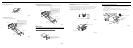
Connection method
2. Clamp firmly with
needle-nosed pliers.
Clamp the parking brake
switch power supply side
lead.
Note:
• The position of the parking brake switch depends
on the vehicle model. For details, consult the
vehicle Owner’s Manual or dealer.
This Product
1.
Yellow
To terminal always supplied with power
regardless of ignition switch position.
Yellow (video input)
(VIDEO INPUT)
15 cm
Fuse resistor
Orange/white
To lighting switch terminal.
Fig. 2
Connecting the Power Cord