


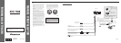
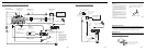
<ENGLISH>Connecting the Units
Multi-Channel AV
Master Unit (e.g. AVM-P9000R)
(sold separately)
Gray
Green
Gray
RCAcable (supplied with
the DVD player)
Blue
Yellow
(DVDVIDEO IN)
IP-BUS cable
(supplied with the Multi-Channel
AVMaster Unit)
Optical cable
(supplied with the Multi-
ChannelAVMaster Unit)
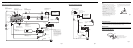
3m
Black
Green
20 pin cable
(supplied)
Blue
Red
RCAcables (sold separately)
Green
Red
To audio outputs
To video output
RGB cable
(supplied with the Multi-
ChannelAVMaster Unit)
Red
Yellow
White (Left)
Red (Right)
AVcable
(supplied with the Multi-
ChannelAVMaster Unit)
Connection box
(supplied with the DVD
Navigation Unit)
DVD Navigation Unit
(e.g.AVIC-9DVD)
(sold separately)
This product
Voiceguidance speaker
(supplied)
3m
DVD player
(e.g. SDV-P7)
(sold separately)
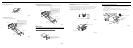
Red
Not used.
Blue
40 cm
Yellow (front
video output)
Yellow/black
ToYellow/black lead
(GUIDE ON)
on the navigation unit.
STAND ALONE
IP-BUS
Normally, connection is not
necessary.
If the DVD player (e.g. SDV-
P7) is installed in a location
that prevents reception of the
remote control signal, connect
with a separately soldAV-BUS
extension cable. (Or connect a
separately sold remote sensor
to the DVD player.)
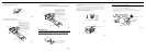
When Connecting the Multi-Channel AV Master Unit
Fig. 3
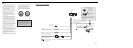
3m
Green
20 pin cable
(supplied)
Red
RCAcable
(sold separately)
To video output
Yellow
(VIDEO INPUT)
Connection box
(supplied with the DVD
Navigation Unit)
DVD Navigation Unit
(e.g.AVIC-9DVD)
(sold separately)
This product
Voice guidance speaker
(supplied)
3m
Red
15 cm
To audio outputs
RCAcable
(sold separately)
To audio inputs of car stereo
When Connecting the Navigation Unit
Fig. 4
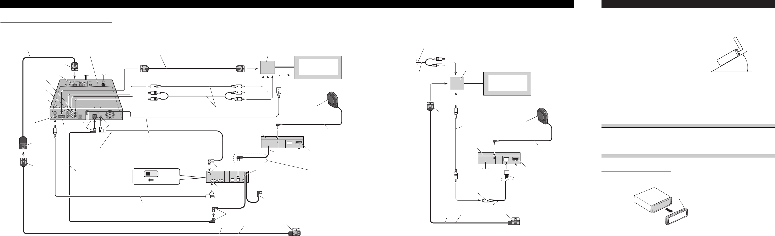
Installation <ENGLISH>
Note:
• Before finally installing the unit, connect the
wiring temporarily, making sure it is all connected
up properly, and the unit and the system work
properly.
• Use only the parts included with the unit to ensure
proper installation. The use of unauthorized parts
can cause malfunctions.
• Consult with your nearest dealer if installation
requires the drilling of holes or other modifications
of the vehicle.
• Install the unit where it does not get in the driver’s
way and cannot injure the passenger if there is a
sudden stop, like an emergency stop.
• Do not place the display in a position where it will
impede the driver’s visibility or affect the opera-
tion of your vehicle’s air bags.
• If installation angle exceeds 30° from horizontal,
the unit might not give its optimum performance.
(Fig. 5)
Fig. 5
30°
DIN Front/Rear-mount
This unit can be properly installed either from “Front” (conventional DIN Front-mount) or
“Rear” (DIN Rear-mount installation, utilizing threaded screw holes at the sides of unit
chassis). For details, refer to the following illustrated installation methods.
DIN Front-mount
Installation with the rubber bush
1. Remove the frame. (Fig. 6)
Fig. 6
Frame
Pull out to remove the frame.
(When reattaching the frame, point the
side with a groove downwards and
attach it.)