


4
1
234
12
34
F
E
D
C
B
A
DEH-1500R/XU/EW
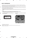
- CD Player Service Precautions
1. Before disassembling the unit, be sure to turn off the
power. Unplugging and plugging the connectors dur-
ing power-on mode may damage the ICs inside the
unit.
2. To protect the pickup unit from electrostatic dis-
charge during serviving, take an appropriate treat-
ment(shorting-solder) by referring to "the DISAS-
SEMBLY" on page 47.
3. After replacing the pickup unit, be sure to check the
grating.(See p.44.)
4. In this product, because the memory capacity of the
microcomputer is insufficient, the test mode is not
installed. However grating of the pickup unit can be
confirmed.
CONTENTS
SAFETY INFORMATION ............................................................................................................................................2
1. SPECIFICATIONS .......................................................................................................................................................5
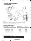
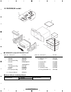
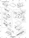
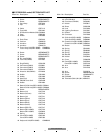
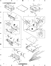
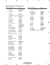
2. EXPLODED VIEWS AND PARTS LIST.......................................................................................................................7
2.1 PACKING(EW model)...........................................................................................................................................7
2.2 PACKING(EE model) ............................................................................................................................................8
2.3 EXTERIOR(EW model).......................................................................................................................................10
2.4 EXTERIOR(EE model) ........................................................................................................................................12
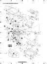
2.5 CD MECHANISM MODULE...............................................................................................................................14
3. BLOCK DIAGRAM AND SCHEMATIC DIAGRAM...................................................................................................16
3.1 BLOCK DIAGRAM ..............................................................................................................................................16
3.2 OVERALL CONNECTION DIAGRAM(GUIDE PAGE) ........................................................................................18
3.3 KEYBOARD UNIT...............................................................................................................................................24
3.4 CD MECHANISM MODULE...............................................................................................................................26
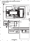
4. PCB CONNECTION DIAGRAM................................................................................................................................30
4.1 TUNER AMP UNIT .............................................................................................................................................30
4.2 KEYBOARD UNIT...............................................................................................................................................34
4.3 CD MECHANISM MODULE...............................................................................................................................36
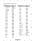
5. ELECTRICAL PARTS LIST........................................................................................................................................38
6. ADJUSTMENT .........................................................................................................................................................43
6.1 CD ADJUSTMENT .............................................................................................................................................43
6.2 CHECKING THE GRATING AFTER CHANGING THE PICKUP UNIT................................................................44
6.3 ERROR MODE ....................................................................................................................................................46
7. GENERAL INFORMATION.......................................................................................................................................47
7.1 DIAGNOSIS ........................................................................................................................................................47
7.1.1 DISASSEMBLY..............................................................................................................................................47
7.1.2 CONNECTOR FUNCTION DESCRIPTION....................................................................................................52
7.2 PARTS.................................................................................................................................................................53
7.2.1 IC ....................................................................................................................................................................53
7.2.2 DISPLAY.........................................................................................................................................................61
7.3 OPERATIONAL FLOW CHART...........................................................................................................................63
7.4 CLEANING..........................................................................................................................................................64
8. OPERATIONS ...........................................................................................................................................................65