


60
1
234
12
34
F
E
D
C
B
A
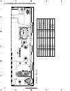
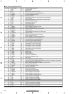
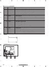
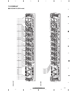
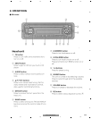
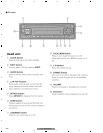
DEH-1500R/XU/EW
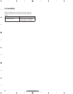
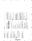
No. Symbol I/O Explain
1 AMANT I AM antenna input AM antenna input high impedance AMANT pin is connected with
an all antenna by way of 4.7µH. (LAU type inductor) A series circuit
including an inductor and a resistor is connected with RF ground for
the countermeasure against the ham of power transmission line.
2 RFGND RF ground
Ground of antenna block
3 FMANT I FM antenna input Input of FM antenna 75Ω Surge absorber
(DSP-201M-S00B) is necessary.
4 VCC power supply The power supply for analog block. D.C 8.4V ± 0.3
V
5 SL O signal level
Output of FM/AM signals level
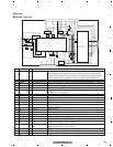
6 CE2 I chip enable-2 Chip enable for EEPROM ” Low” active
7 WC I write control Y
ou can write EEPROM, when EEPROM write control is “ Low” .
Ordinary non connection
8 CE1 I chip enable-1 Chip enable for AF•RF ” High” activ
e
9 CK I clock
Clock
10 DI I data in
Data input
11 NC non connection
Not used
12 OSCGND osc ground Ground of oscillator block
13 ROM_VDD power supply Power supply for EEPROM pin 13 is connected with a power supply of
micro computer.
14 DO O data out
Data output
15 DGND digital ground
Ground of digital block
16 NC non connection
Not used
17 VDD_3.3 power supply The power supply for digital block. 3.3V ± 0.2
V
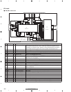
18 NC non connection
Not used
19 NC non connection Not used
20 NC non connection
Not used
21 NC non connection
Not used
22 AUDIOGND audio ground Ground of audio block
23 L ch O L channel output FM stereo “ L-ch” signal output or AM audio output
24 R ch O R channel output FM stereo “ R-ch” signal output or AM audio output
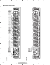
FMRF
ANT adj
RF adj
FM ANT
T51
CF52
CF51
RFGND
OSCGND
DGND
AUDIOGND
NC
VCC
VDD_3.3
3.3V
2.5V
IC 4
3.3V 2.5V
←
IC 2
2.5V
WC
CE2
ROM_VDD
SL
DI
CK
CE1
NC
DO
NC
NC
NC
NC
7 6 13 5 10 9 8 11 14 18 19 20 21
1
3
212 152216 4
17
IC 1
3.3V
AM ANT
FMRF
ATT
LPF
OSC
IC 3 EEPROM
5.0V
IC 5
5V 3.3V
←
ATT
MIXER, IF AMP
DET, FM MPX
24
23
Rch
Lch
- FM/AM Tuner Unit
EE model