


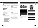
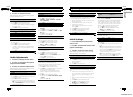
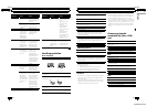

1 Power cord input
2 Rear output or subwoofer output
3 Antenna input
4 Fuse (10 A)
5 Wired remote input
Hard-wired remote control adaptor can be
connected (sold separately).
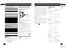
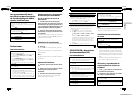
Power cord
Perform these connections when not connect-
ing a rear speaker lead to a subwoofer.
1
8
9
c
d
6
32
4
5
7
a
b
e
f
h
g
LR
F
R
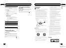
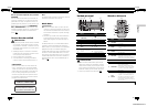
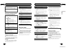
Perform these connections when using a sub-
woofer without the optional amplifier.
1
8
9
c
d
6
32
4
7
a
b
a
b
e
f
h
g
LR
F
SW
i
j
d
c
k l
1 To power cord input
2 Left
3 Right
4 Front speaker
5 Rear speaker
6 White
7 White/black
8 Gray
9 Gray/black
a Green
b Green/black
c Violet
d Violet/black
e Black (chassis ground)
Connect to a clean, paint-free metal location.
f Yellow
Connect to the constant 12 V supply terminal.
g Red
Connect to terminal controlled by ignition
switch (12 V DC).
h Blue/white
Connect to system control terminal of the
power amp or auto-antenna relay control
terminal (max. 300 mA 12 V DC).
i Subwoofer (4 Ω)
j When using a subwoofer of 70 W (2 Ω), be
sure to connect the subwoofer to the violet
and violet/black leads of this unit. Do not con-
nect anything to the green and green/black
leads.
k Not used.
l Subwoofer (4 Ω)× 2
Notes
! With a 2 speaker system, do not connect any-
thing to the speaker leads that are not con-
nected to speakers.
! Change the initial setting of this unit. Refer to
SW CONTROL (rear output and subwoofer set-
ting) on page 9.
The subwoofer output of this unit is monaural.
En
12
Section
03
Installation
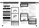
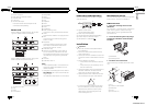
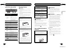
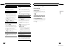
Power amp (sold separately)
Perform these connections when using the
optional amplifier.
1
3
2
4
55
1 System remote control
Connect to Blue/white cable.
2 Power amp (sold separately)
3 Connect with RCA cable (sold separately)
4 To Rear output or subwoofer output
5 Rear speaker or subwoofer
Installation
Important
! Check all connections and systems before
final installation.
! Do not use unauthorized parts as this may
cause malfunctions.
! Consult your dealer if installation requires dril-
ling of holes or other modifications to the vehi-
cle.
! Do not install this unit where:
— it may interfere with operation of the vehi-
cle.
— it may cause injury to a passenger as a re-
sult of a sudden stop.
! The semiconductor laser will be damaged if it
overheats. Install this unit away from hot
places such as near the heater outlet.
! Optimum performance is obtained when the
unit is installed at an angle of less than 60°.
60°
! To ensure proper heat dispersal when using
this unit, make sure you leave ample space
behind the rear panel and wrap any loose
cables so they are not blocking the vents
when installing the unit.
DIN front/rear mount
This unit can be properly installed using either
front-mount or rear-mount installation.
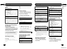
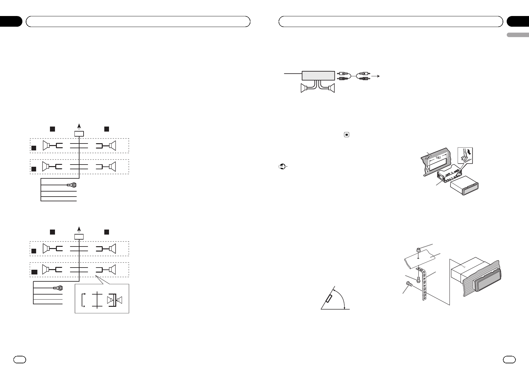
DIN Front-mount
1 Insert the mounting sleeve into the
dashboard.
For installation in shallow spaces, use the sup-
plied mounting sleeve. If there is enough
space, use the mounting sleeve that came
with the vehicle.
2 Secure the mounting sleeve by using a
screwdriver to bend the metal tabs (90°)
into place.
1
2
1 Dashboard
2 Mounting sleeve
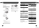
3 Install the unit as illustrated.
Use commercially available parts when instal-
ling.
1
2
3
4
5
1 Nut
2 Firewall or metal support
3 Metal strap
4 Screw
5 Screw (M4 × 8)
En
13
English
Section
03
Installation
<CRD4530-A/N>7